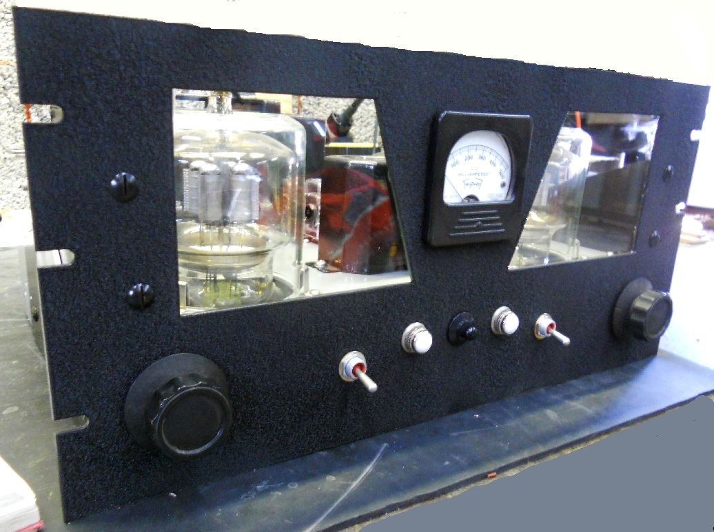
4CX250B Linear
Amplifier
|
The latest project (Dec 2018) is a medium-power, all-band linear amplifier utilizing a pair of 4CX250B power tetrodes in a grid-driven configuration for 900 watts pep output. Clicking
here or on the image at left goes to the amplifier web page
|
|
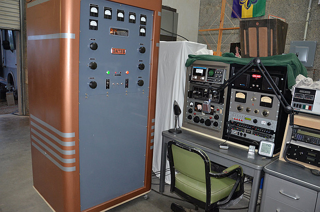
Current KB7OCY Operating Position |
The
Gates
BC-250GY operating position at KB7OCY. Click on link
below for more information: |
|
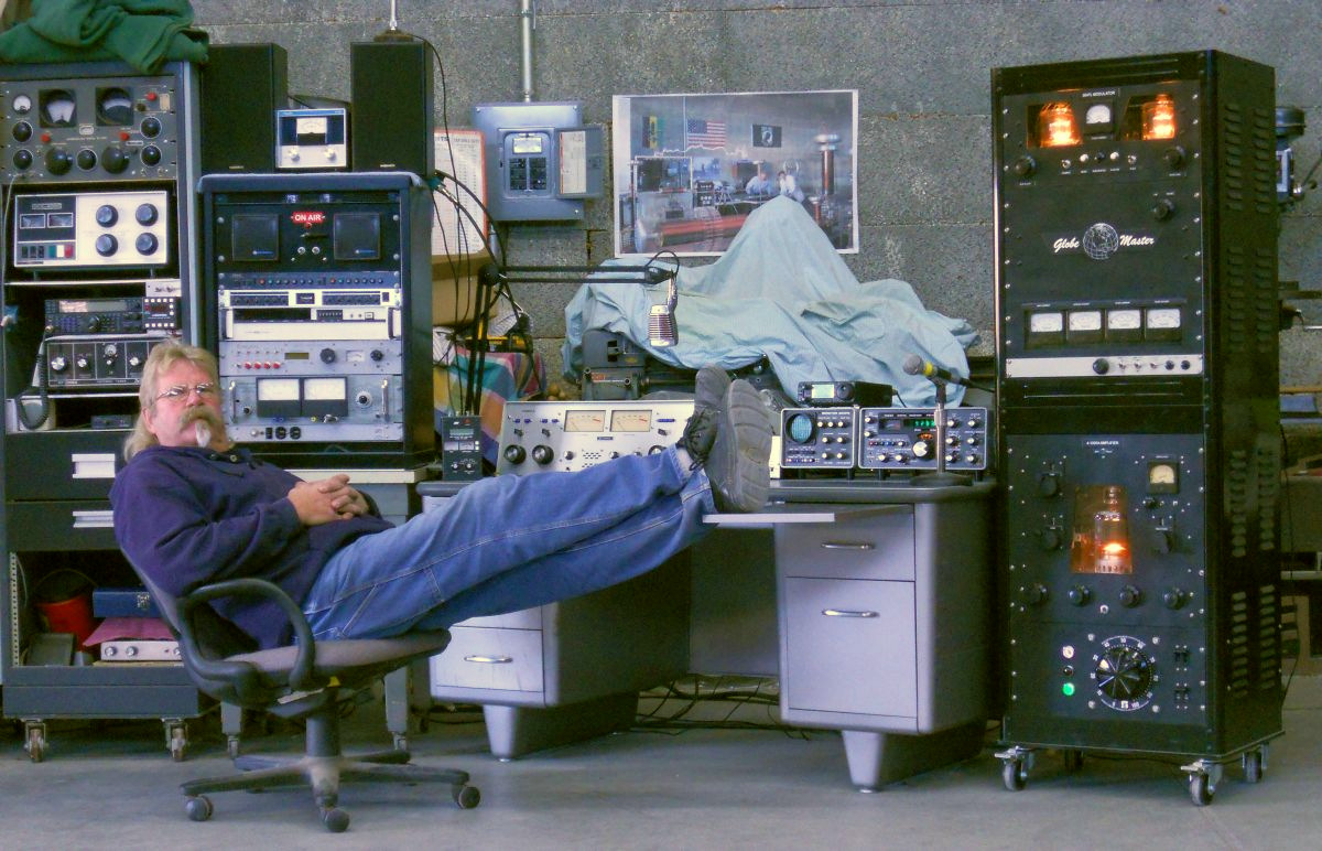
Previous KB7OCY Operating Position
|
The operating position
used with the GLOBE MASTER AM transmitter . It runs a 4-1000A
final modulated by a pair of 304TL's (described below) for an
easy full-legal-limit power outputwith less than 10 watts of
drive. CLICKING HERE or on the image at left |
|
Globe Master Transmitter
Technical Manual
|
The detailed circuit description and parts layout of the Globe Master transmitter have been compiled into a Technical Manual by KB7OCY. This manual was the basis for the two-part article in the Jan. and Feb. 2014 issues of Electric Radio magazine. The link below goes to an HTML, web-page version of that manual. CAUTION:
This
is a large document, CLICKING HERE or on the image at left |
|
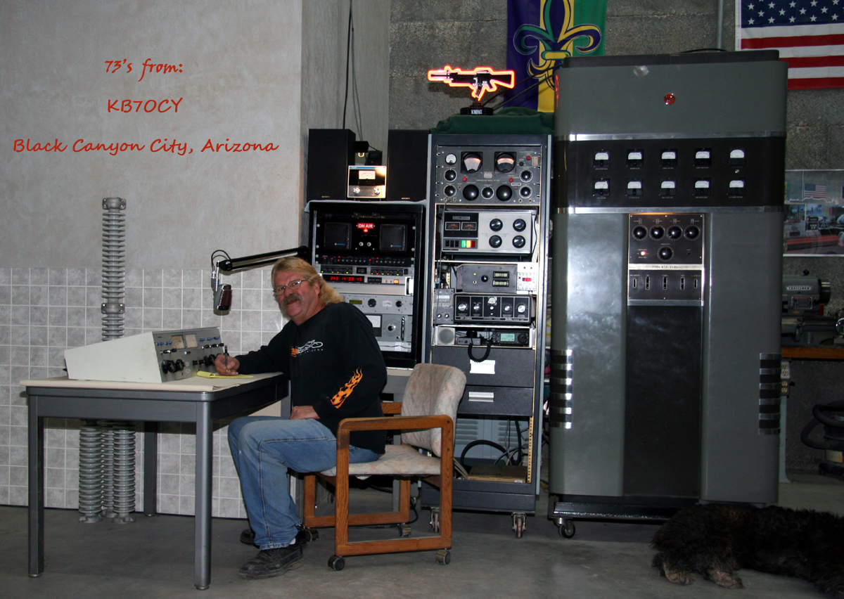
Even Earlier Operating Position
|
Earlier on-the-air rigs at KB7OCY: At right is an RCA BTA-250L ex-broadcast transmitter running 250 watts AM on 160 meters. It is paired with the Hammarlund SP-600jx receiver in the top of the middle rack. Immediately below is a National Radio NCL-2000 vintage linear amplifier that is used with an Icom 706 and Dentron antenna tuner for SSB operations on the higher bands. The audio chain occupies the leftmost rack and consists of a Behringer microphone preamp driving a Yamaha compressor/limiter which then feeds line-level audio to the Harris console and on to the RCA transmitter. Views of
the inside of the RCA transmitter and its schematic diagram A video
guided tour of the RCA transmitter and rack equipment CLICKING
HERE
or on the image at left |
|
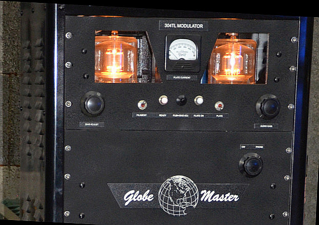
Globe Master 304TL Modulator
Power Test
|
Full-power testing was the latest step
taken in the development of the 304TL Modulator Deck.
The results were quite satisfactory. CLICKING HERE or on the image at left brings up a larger version of this photo (1200 x 670 px, 664 kB). CLICKING
HERE
______ takes you to an index page for all the
modulator-test images and additional comments by KB7OCY. takes you to a YouTube video of a test with the modulator driving an 833-based Tesla coil that gives rather fiery results. |
|
Globe Master Modulator
Schematic Diagram
|
CLICKING HERE ______ takes you the detailed modulator schematic pages. This will open a PDF file of approximately 4.7 Megabytes showing the very neat, hand-drawn schematics and wiring diagrams of the entire modulator. | |
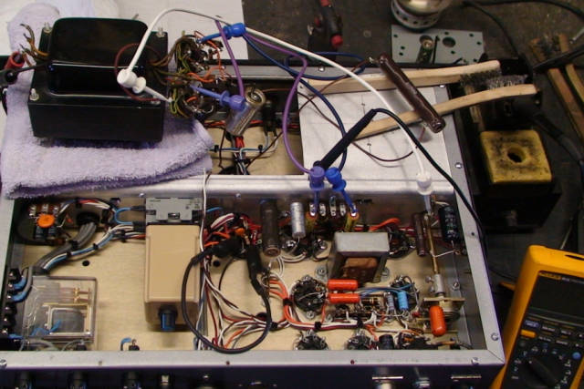
Globe Master Modulator
Driver Test
|
The modulator speech-amp and
driver stages were first tested separately into a local
speaker for fidelity and power output with good results. CLICKING HERE takes you to additional photos of the set-up . CLICKING HERE takes you to a YouTube video of the actual test. |
|
Globe Master 304TL Modulator Project |
Re-engineering this
modulator deck was the first project undertaken in restoring a
multi-band, multi-rack set of vintage AM transmitters
originally owned and operated by W7GNP in Phoenix. The
units were in a very sad state and did not look like this
finished one at all. However, transformer iron is quite
rugged and progress has been forthcoming. -air rigs CLICKING HERE or on the image at left brings up a larger version of this photo (1034 x 773 px, 614 kB). CLICKING
HERE
______
takes you to an index page for all
the modulator and power-supply progress images |
|
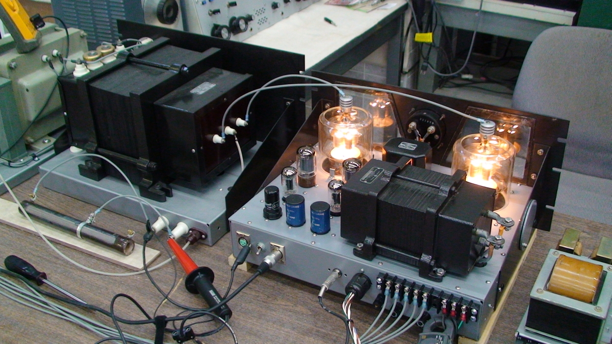
Globe Master 304TL Modulator Project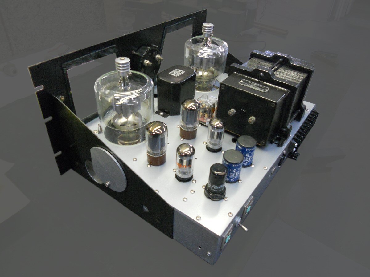 |
Rear view of the modulator deck
in almost-finished form. The large transformer on the
left rear of the chassis is NOT the modulation
transformer. Rather it is a 5-volt, 60-amp filament
transformer for the 304TL's. CLICKING HERE or on the image at left brings up a larger version of this photo (1167 x 877 px, 267 kB). CLICKING HERE _______ takes you to an index page for all the modulator and power-supply progress images |
|
Globe Master 304TL Modulator Project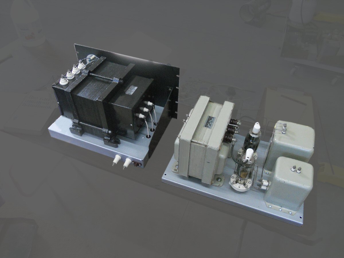 |
THIS is the modulation
transformer, professionally rewound on a 2.2 kVA core by the
original builder CLICKING HERE or on the image at left brings up a larger, complete version of this photo (1200 x 800 px, 850 kB). CLICKING HERE ________ takes you to an index page for all the modulator and power-supply progress images |
|
 |
CLICKING HERE or on the image at left takes you to Henry's Tesla Coil website for some electrifying images of truly high-voltage RF at work and play . (Once there, click on the 833A tube in the center to enter the domain of the eminent Dr. Hankenstein). | |
")
