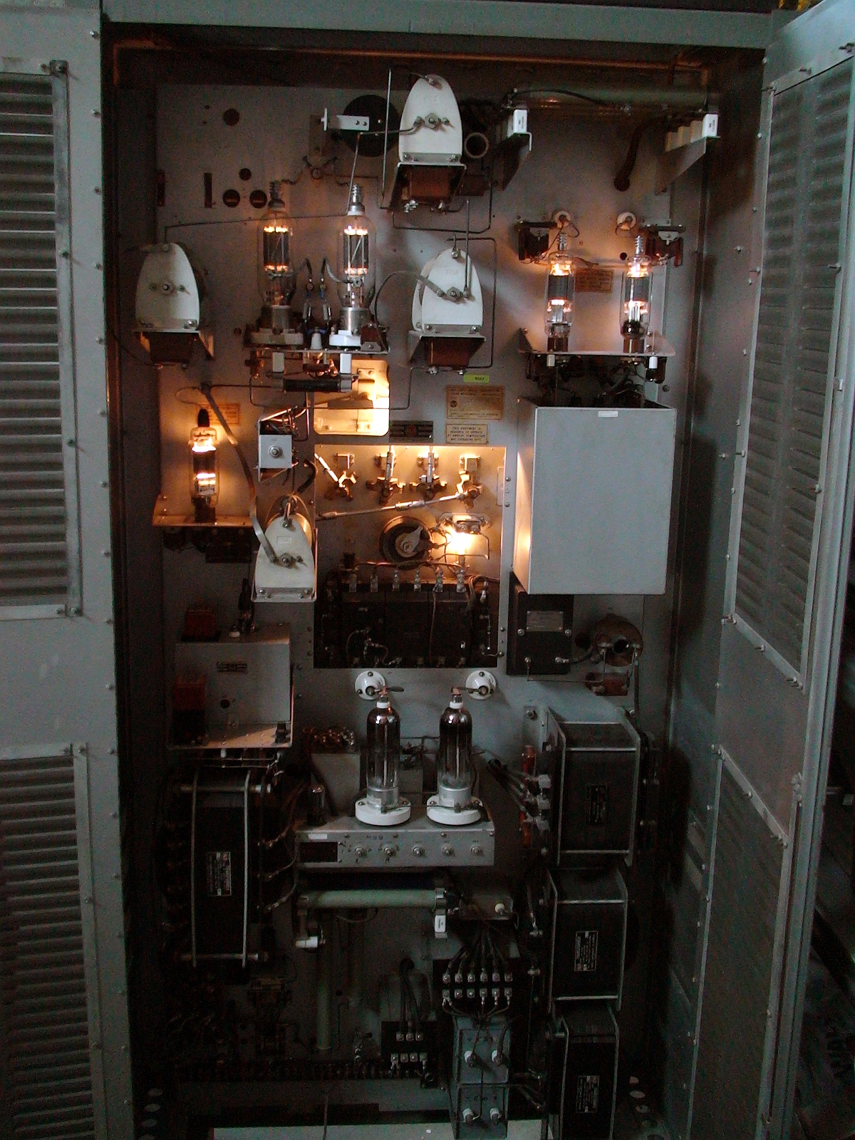
BTA-250L Tube Layout
|
The room-filling, warm glow of thoriated-tungsten filaments is decidedly attenuated with the BTA-250L hiding its tubes behind its front panel. This photo through the back doors shows the generously spaced transmitter components. Prominent at upper left are the 810 finals which produce 250 watts of carrier output power, while to the right are the 828 modulators. The driver 828 is to the extreme left and the 8008 mercury-vapor rectifiers that supply the 1600-volt B+ power are bottom center. Clicking
HERE or on the image at left brings up
a larger version of the
photo showing much greater detail (1.5 MB). A video guided tour of the RCA transmitter and rack equipment can be found HERE (YouTube). |
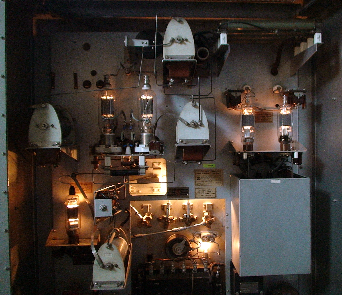
Tube Layout Close-up
|
This
transmitter was originally acquired by Patrick, KD5OEI, from KNSS in
Wichita, Kansas after it had been on the air there for 50 years on 1330
kc. It was passed-on to KB7OCY where it was completely restored
and a carbonized arc-path at the base of the HV rectifiers
eliminated. Manufactured in the late 1940's, the BTA-250L became
a mainstay of local (Class D, 250-watt) AM-radio broadcasters until the
1960's when they were allowed to increase their daytime power to 1000
watts.
-air
rigs Clicking
HERE or on the image at left brings up
a larger version of the
photo showing much greater detail (1.5 MB). Clicking HERE goes to KD5OEI's web page for THIS transmitter. (off-site link, opens in new window or tab). |
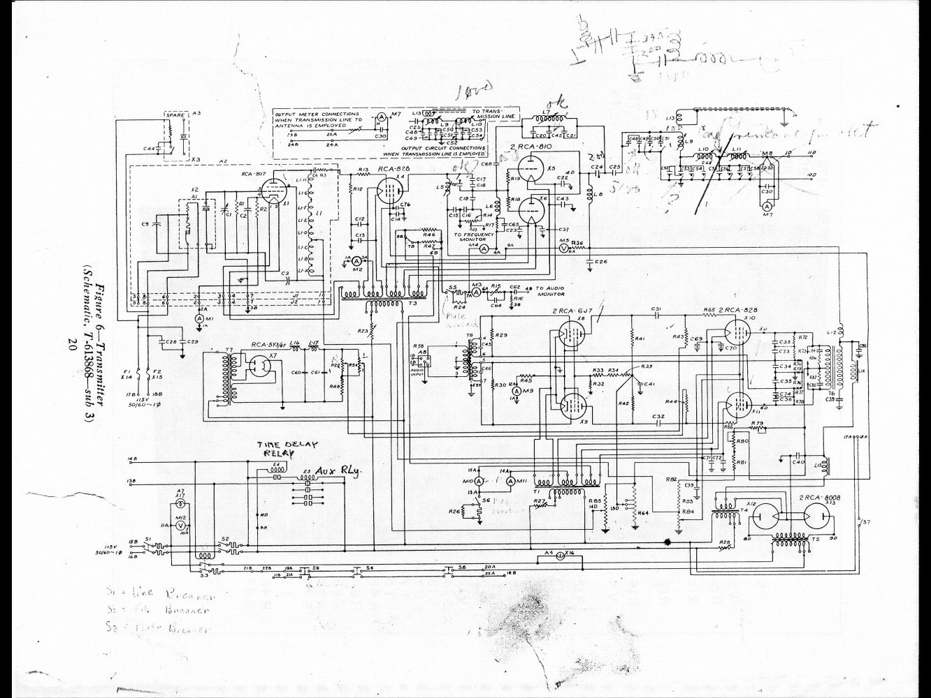
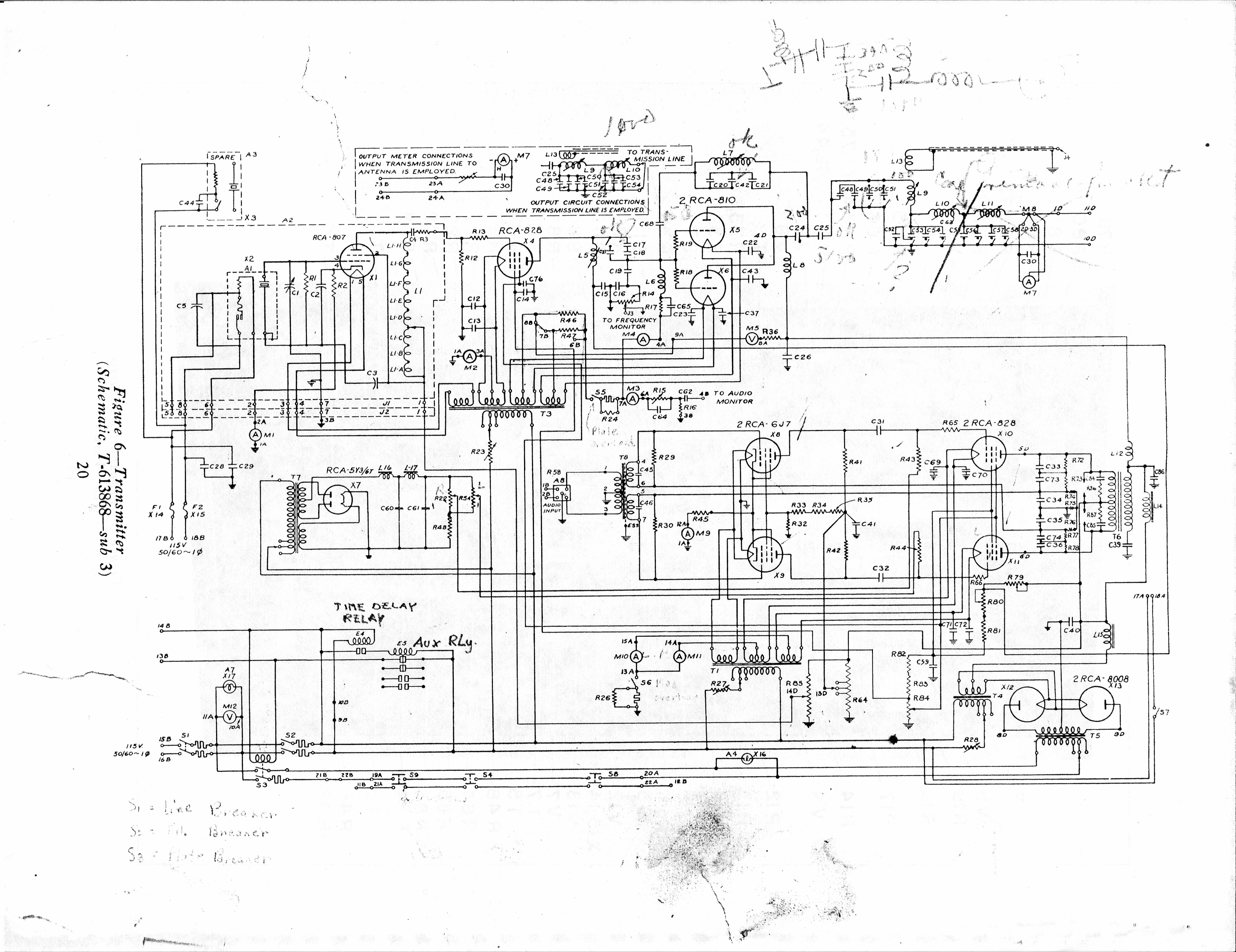
RCA BTA-250L Schematic Diagram
|
Schematic
diagram excerpt showing final amplifier and modulator electrical
configuration. See the full-sized versions linked below for
complete details. Clicking
HERE or on the image at left brings up
a larger version of the diagram showing greater detail (1300 x 1000 px, 400 KB). ___Clicking
HERE brings up the largest version of the diagram (4000 x 3000 px, 2.25 MB).
|