KB7OCY Gates
BC-250GY Transmitter
Back to
KB7OCY Main Page
|
|
||
|
|
|
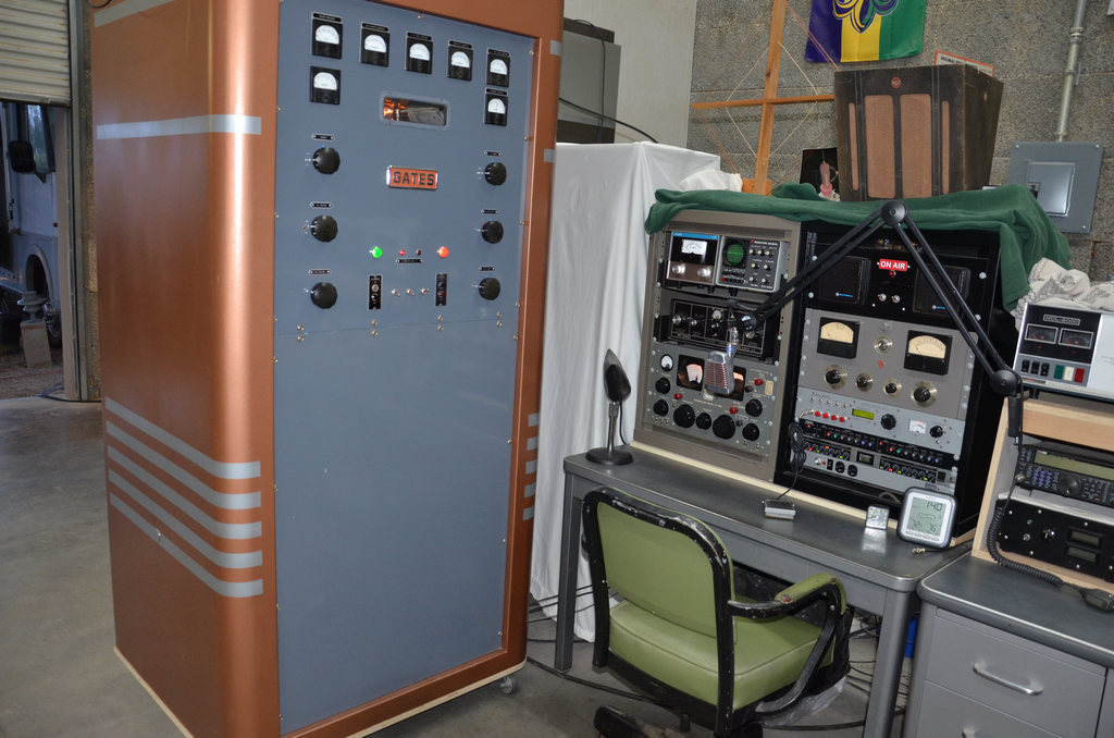
The
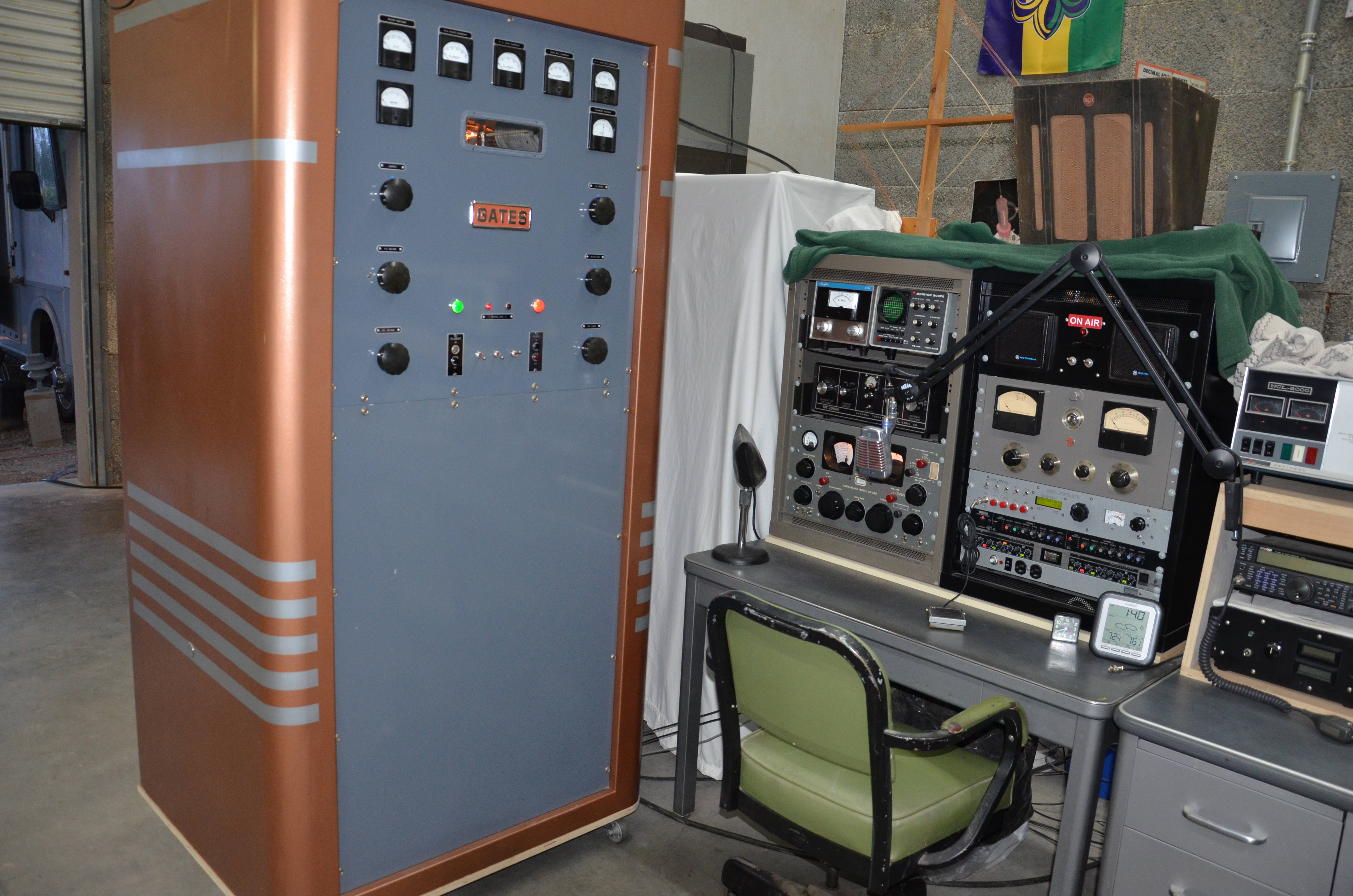
BC-250GY operating position at KB7OCY features a Hammarlund
SP-600 general-coverage receiver, an RCA modulation meter, an MFJ
antenna tuner and a Kenwood station monitor. Microphone audio is
processed by a Behringer equalizer and Yamaha compressor. A very
stable and accurate RF carrier is generated by the WA1FFL DDS VFO that
feeds the transmitter's former crystal oscillator. (Click here
for a 1024x768 photo ~200K)
|
|
|
||
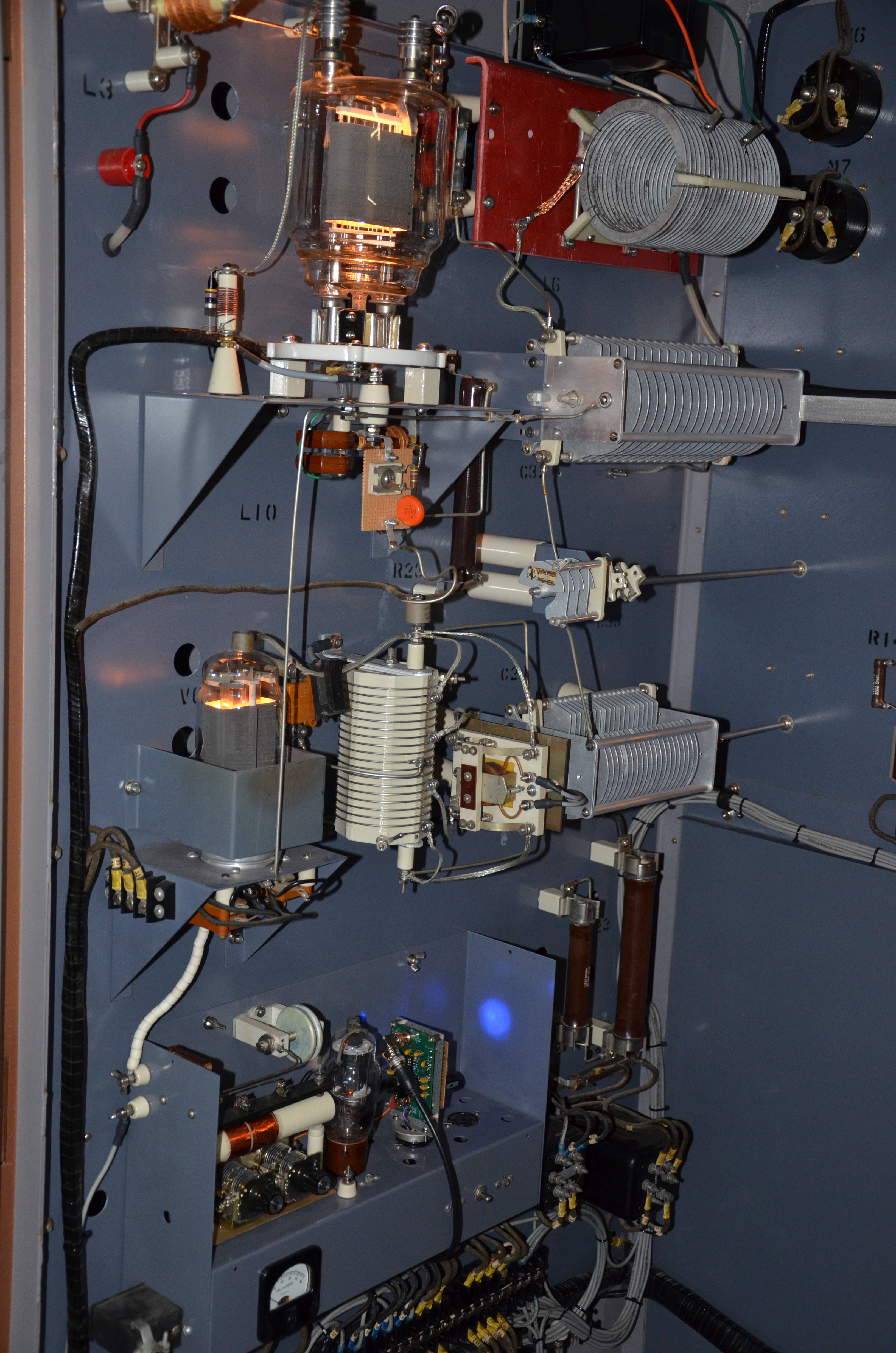 |
The
BC-250GY RF section is mounted on the left side of the cabinet as view
from the back. All components are widely spaced for natural air
cooling and easily accesible by actually walking into the
transmitter. The tube lineup is an 807 buffer feeding an 813
driver which feeds an 833A final amplifier. The transmitter was modified to operate on the 80- and 40-meter amateur bands by means of Westinghouse SG-series relay switching. Most of the original high-power RF tuning components were reused, including the final loading capacitor located on the opposite side of the enclosure. Additionally, the final amplifier was changed from the original pair of 810's to a single 833A. This was facilitated by the filament power being identical for both configurations. The 833A provides an additional 100 watts of plate dissipation and is more readily available than 810's. The 500-watt version of this transmitter runs this same tube line-up, but with increased B+ on the final and modulators. The original 807 crystal oscillator was modified into a buffer amplifier to be driven by an on-frequency VFO at low level. Additional interface and tuning circuitry for each band was incorporated on outboard circuit boards. The grid of the following 813 is untuned. (Click here for a Hi-Res 5Kx3K photo ~1.5_Megabytes) |
|
|
|
||
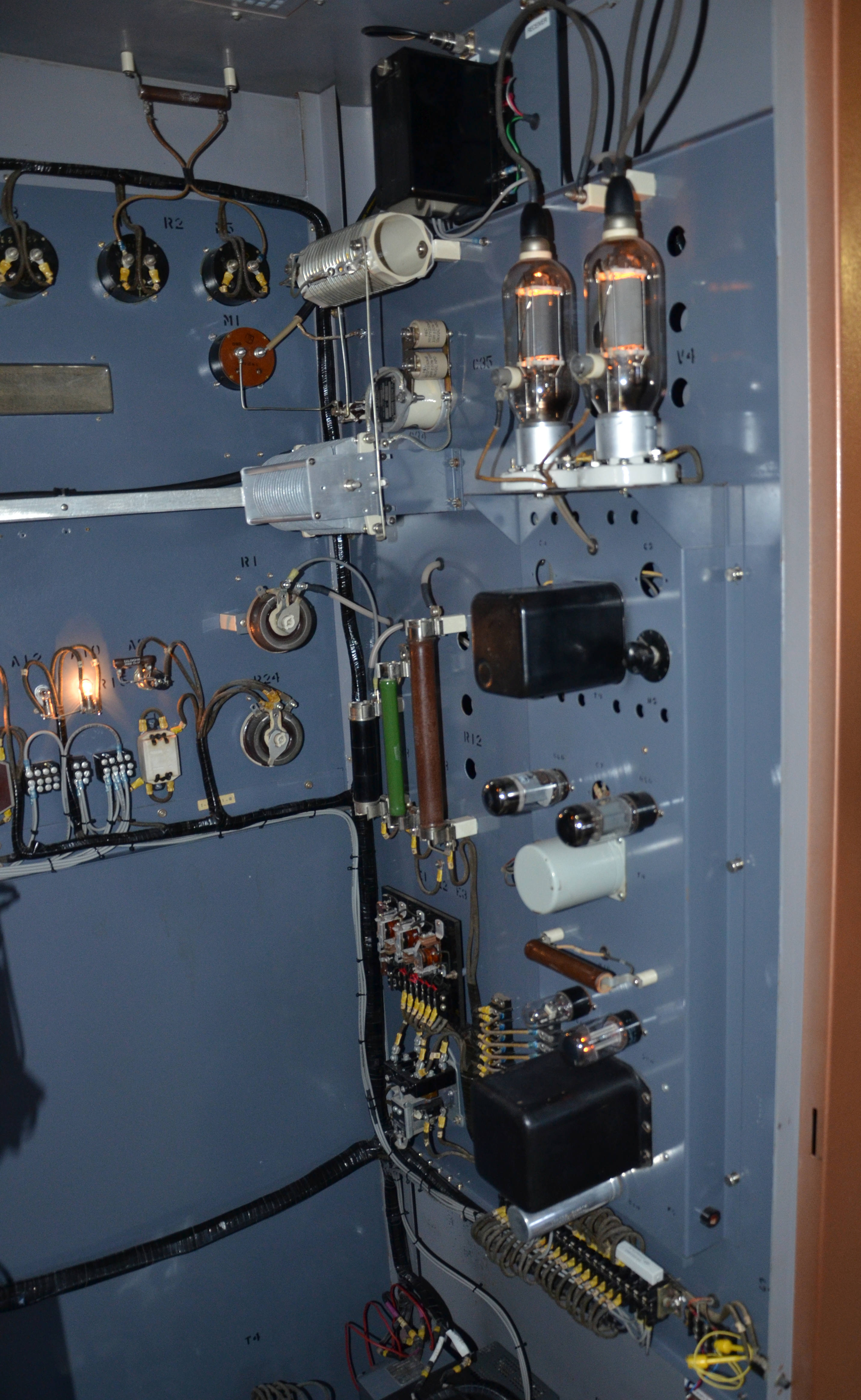 |
The
BC-250GY modulator. It was left in stock configuration, with a
pair of 6L6's for the input/driver stage followed by a pair of
810's. In spite of the increased load of the 833A final, the
810's are still able to achieve 100% modulation at a 375-watt carrier
output level. The variable and fixed capacitors and tapped RF inductor on the top rear of the subassembly comprise the loading controls for the final amplifier. In the original MF design, these components were connected to the plate-tuning controls by an aluminum bus bar. This was replaced with a length of RG-213 coax to limit stray E&H fields at the higher HF frequencies. (Click here for a Hi-Res 5Kx3K photo ~1.5_Megabytes) |
|
|
|
||
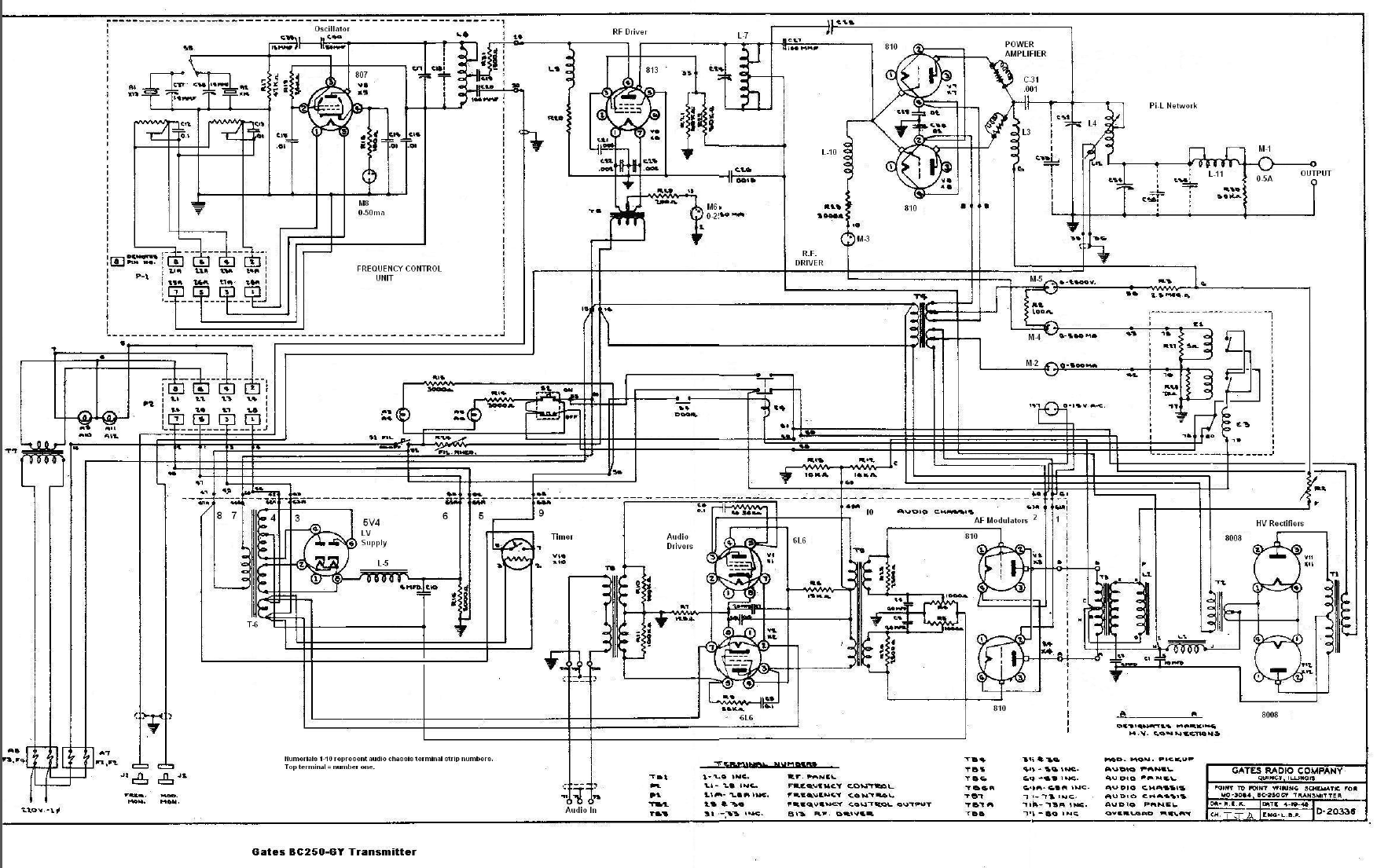 |
The
original BC-250GY schematic, shown for reference only. (Tnx BAMA) (Click here for a larger, 2Kx1K diagram ~475_Kilobytes) |
|
|
|
||
 |
The
"heavy metal" for the BC-250GY. The power supply components are
on the left and the modulator 'iron' is on the right. The
original 8008 mercury-vapor rectifiers were replaced (regrettably) with
plug-in, solid-state substitutes. The modulation transformer in
the right, rear is not the original Gates unit. (Click here for a Hi-Res 5Kx3K photo ~1.5_Megabytes) |
|
|
| ||
|
| ||
|
| ||