KB7OCY Modulator/Power Supply Restoration
(Back to KB7OCY Main Page)
1950's AM Rig
1.87 MB |
AM Rig-mod section
630.70 KB |
AM Rig-mod-rear
1.71 MB |
6 mtr-BB gun.jpg
679.76 KB |
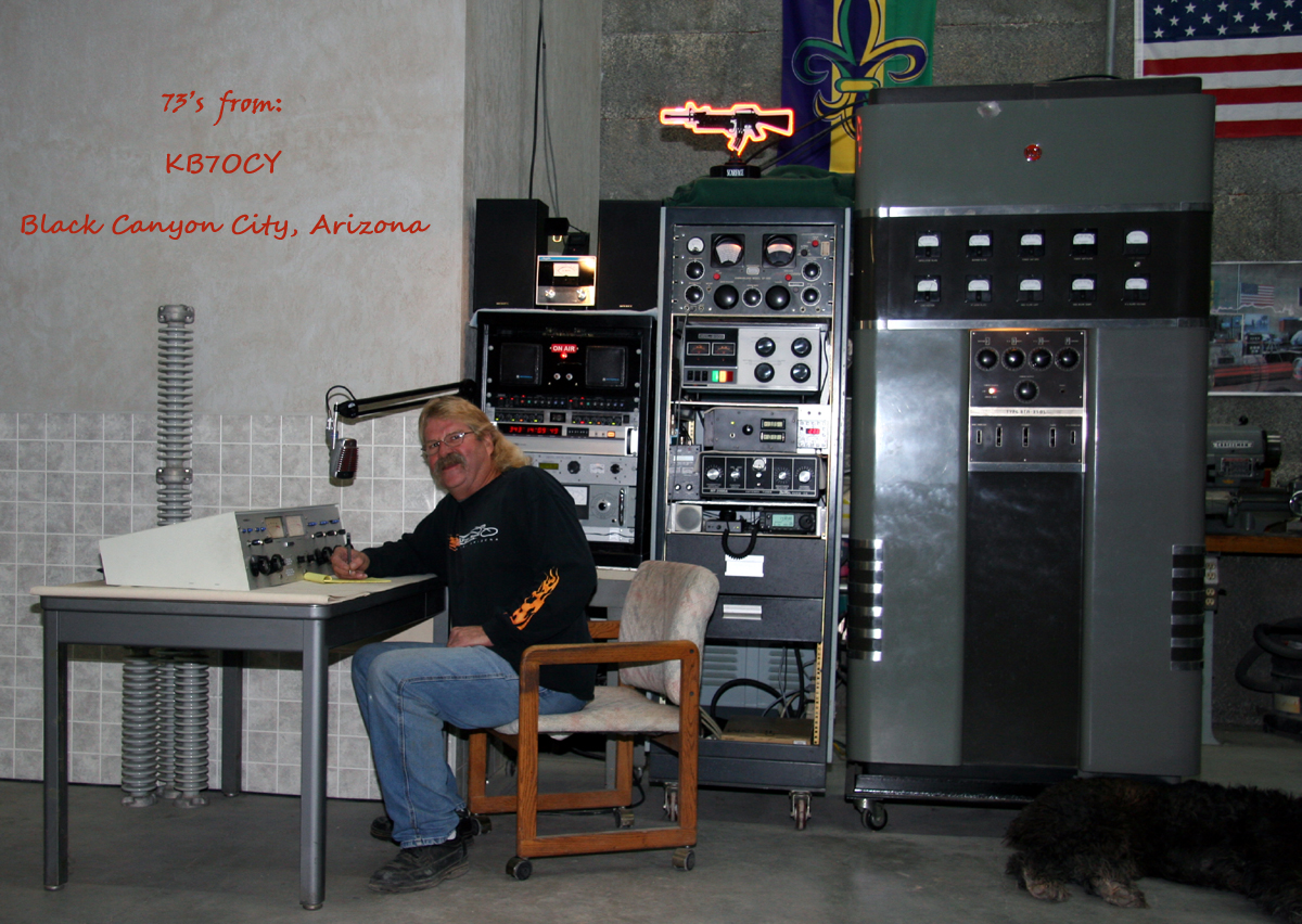
73's from KB7OCY.jpg
837.88 KB |
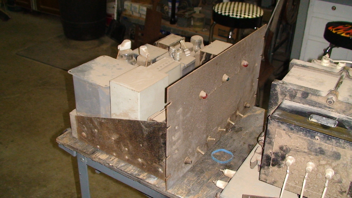
1st layout-not good
978.47 KB |
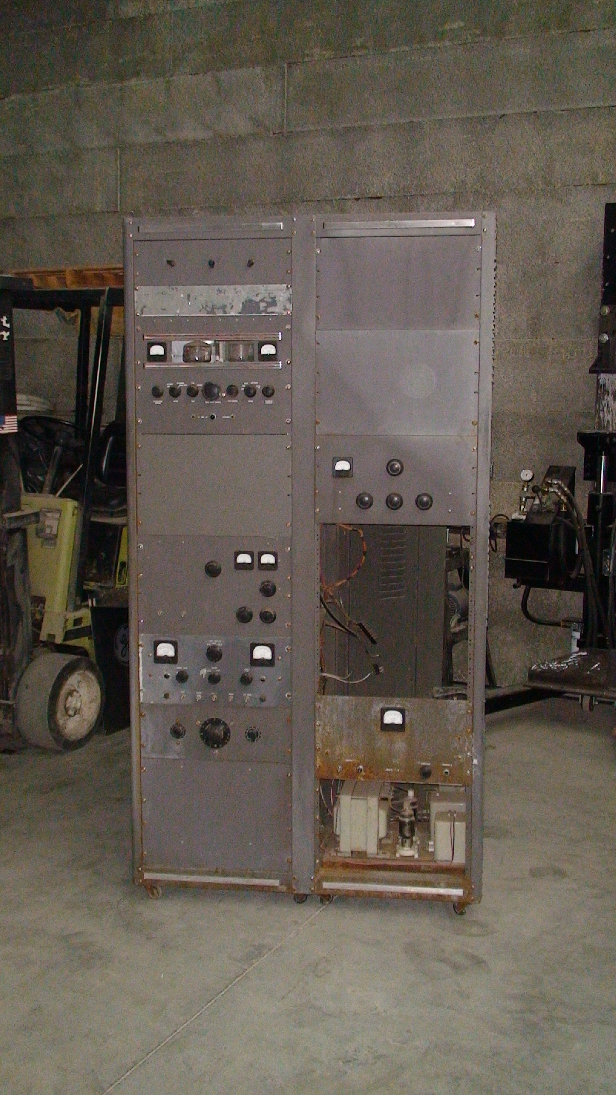
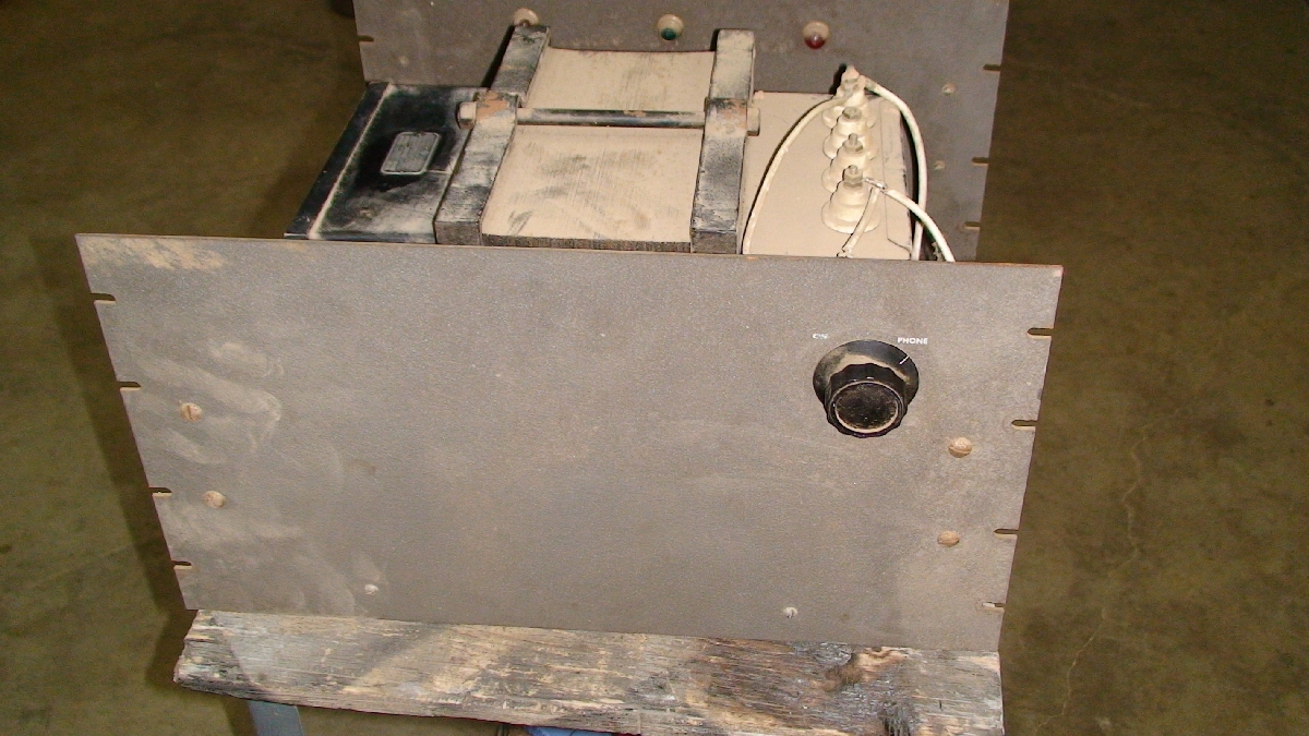
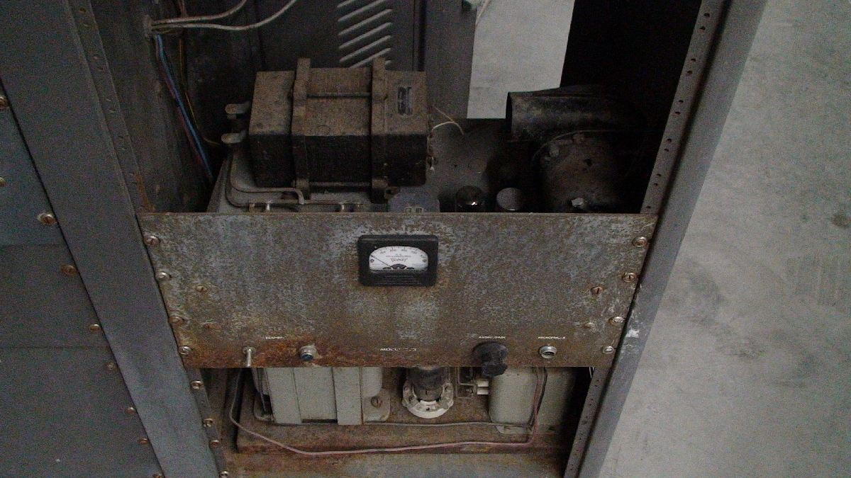
KB7OCY writes: I received from a fellow ham, Jim W7GNP, an entire dual-rack, 80"-tall transmitter with three transmitters, two power supplies and one humongous modulation transformer. My buddy Fred and I dragged this beast out from the outside eaves where it had been sitting for who knows how many years, slid it onto our trailer with a winch, and brought it home. It was physically in very poor condition: lots of rust, tubes shot out from kids with BB guns, etc. BUT, all the pieces from an original 1950's home brew build were all intact! Actually attempting to build a project like this without an entire garage full of "vintage" junk these days might take years of dedicated hunting for parts... but there it was... complete! |
|||||
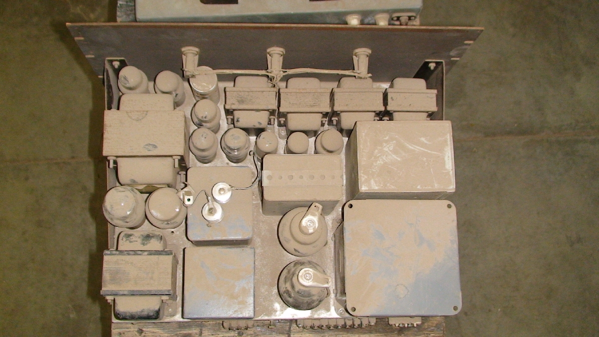
main power supply
1.70 MB |
main pwr supp-01
625.69 KB |
main pwr supp-02
616.78 KB |
old mod deck fils on
998.90 KB |
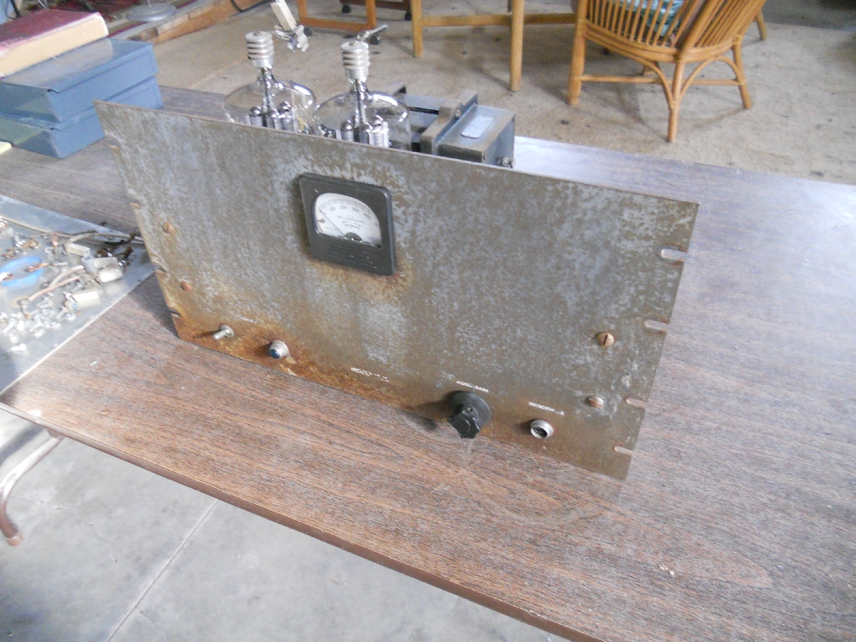
old mod deck-front
924.57 KB |
old pwr supp test
1.01 MB |
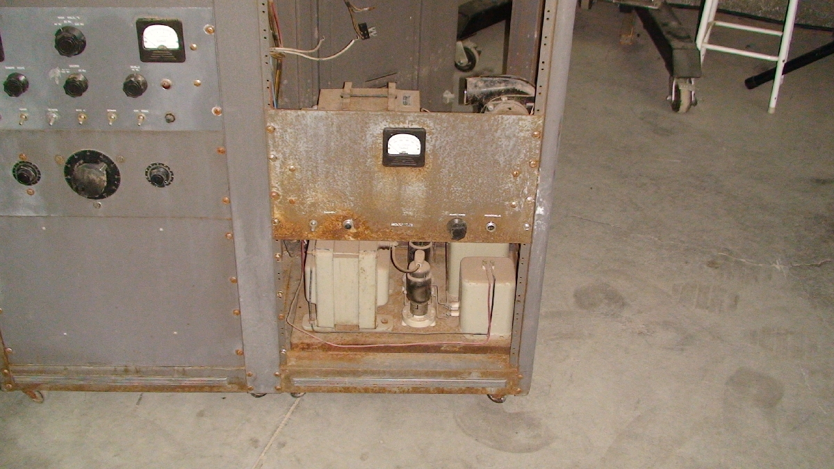
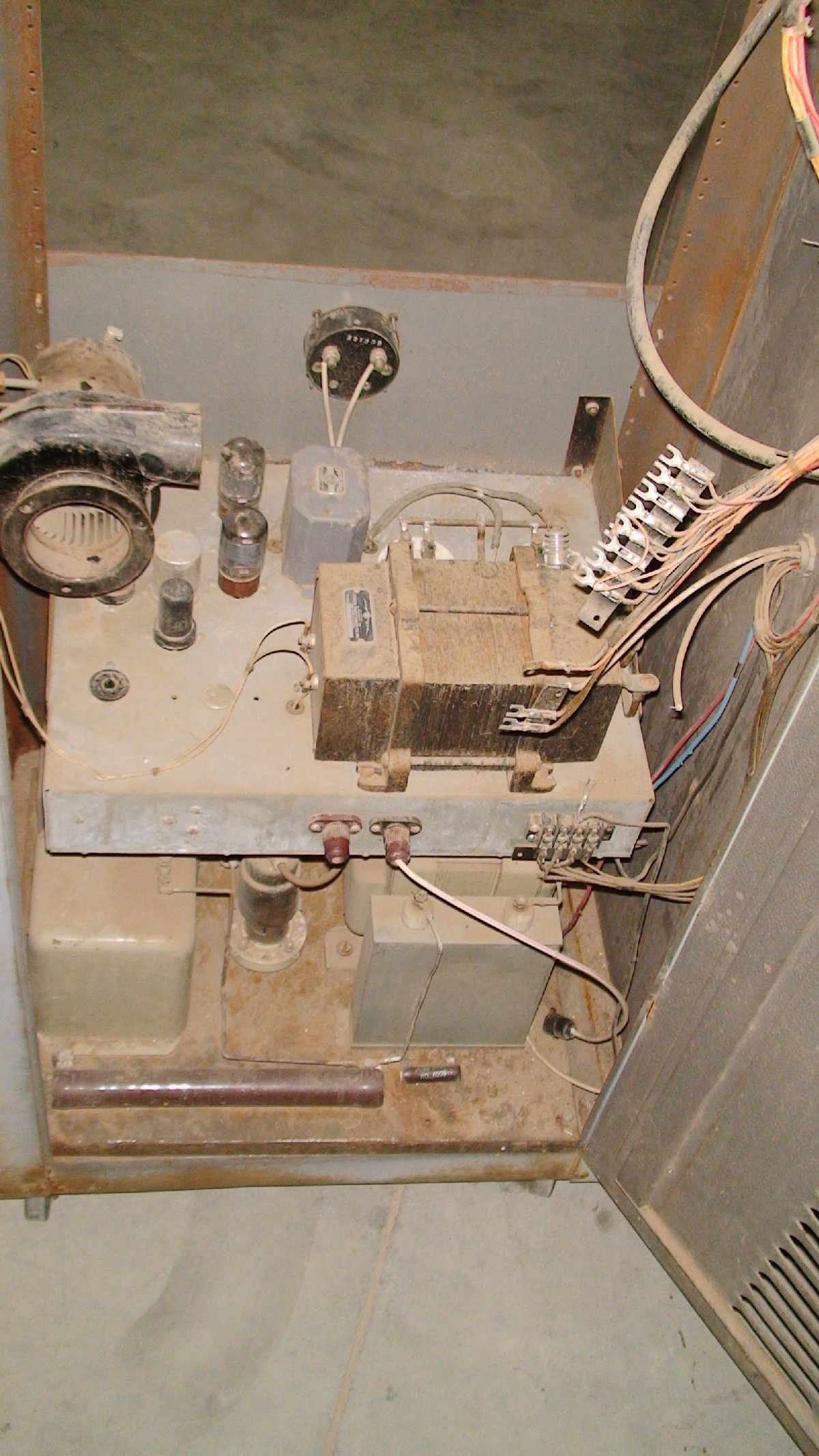
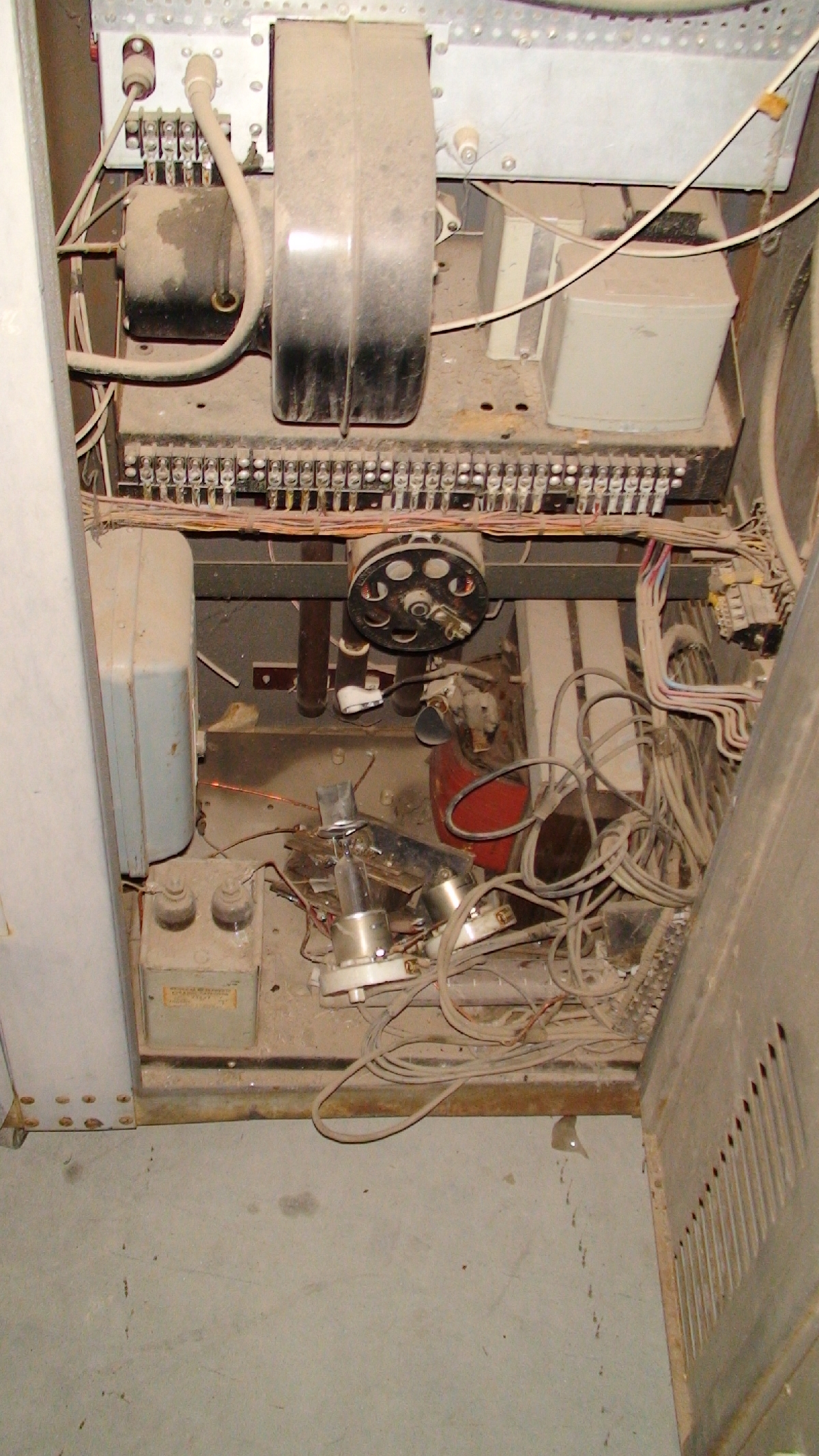
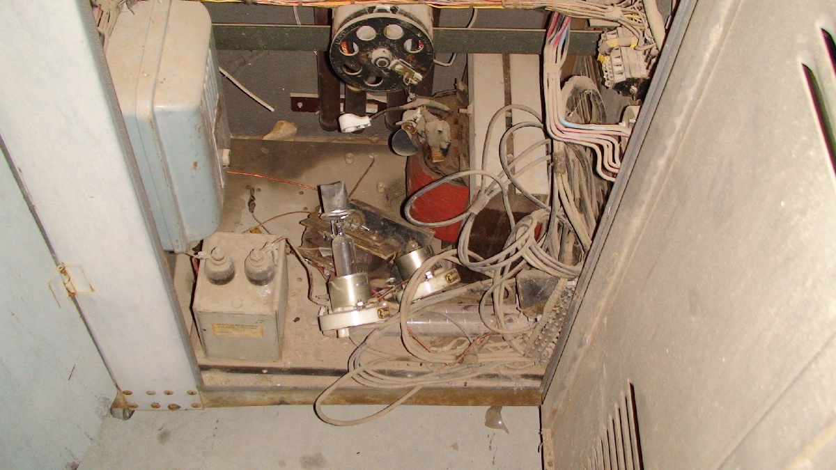
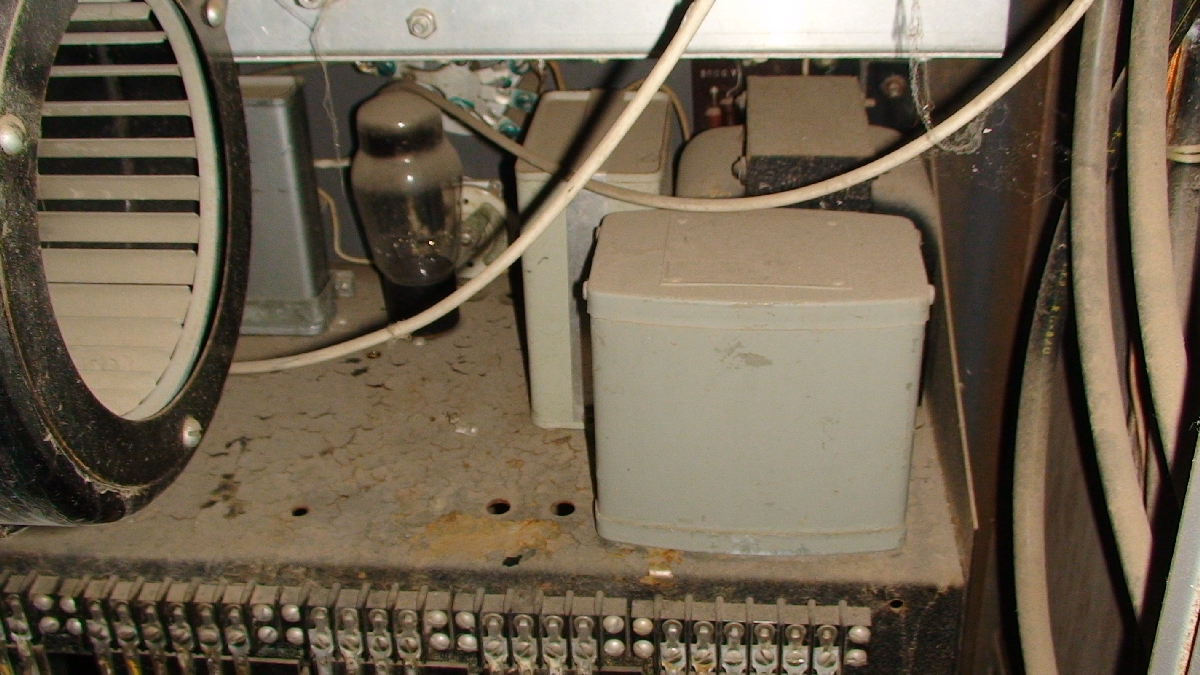
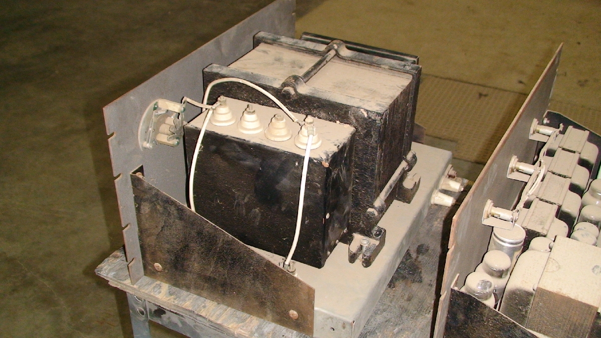
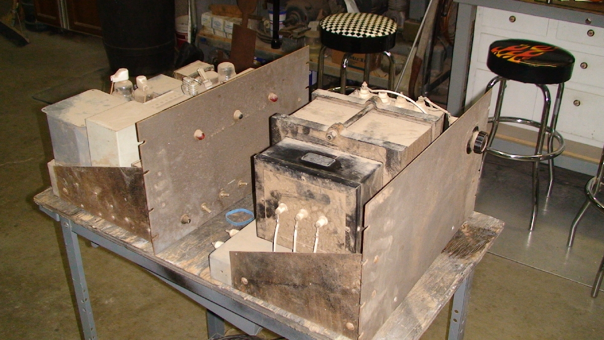
Here's a little history I have gathered on this rig so far: Jim told me that the rig was originally built by the Fenwick triplets as a high school project sometime in the fifties. Are you kidding me? High schooler's built this awesome rig? Apparently their father was an electrical engineer who worked at a motor/transformer rewind shop on East Jefferson and had the giant 2200VA filament transformer rewound into a modulation transformer... I guess they were after the large iron content of the core. I began speaking with a few other hams who told me that they have seen it go from one estate to another, some wishing to buy it, but it was just "too heavy" to deal with. I have also been told that when this rig was on the air, the audio quality rivaled that of commercial stations. From what I gather, the three transmitters are 50, 144 and 220mhz units. The main power supply for the transmitters was a pullout from a 2400 volt distribution transformer. The modulator's power supply is on its own chassis and is rated at 3kv / 500mA, has a pair of 3B28 mercs, a choke and an oil capacitor. |
|||||
refurb pwr supp test
1016 KB |
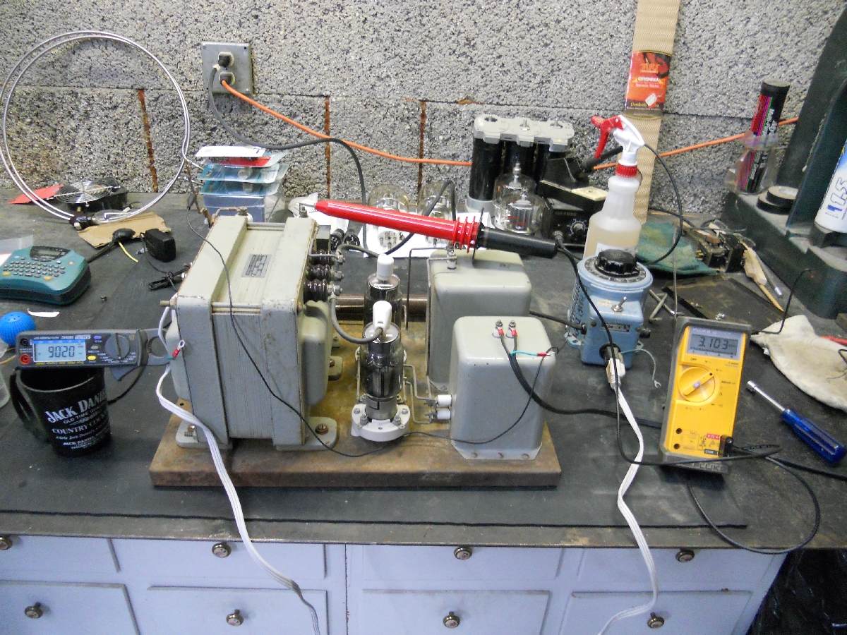
mod xfmr & PS
859 KB |
old mod xfmr back
658 KB |
old mod xfmr front
617 KB |
old mod xfmr front
684 KB |
mod xfmr-spark gap
865 KB |
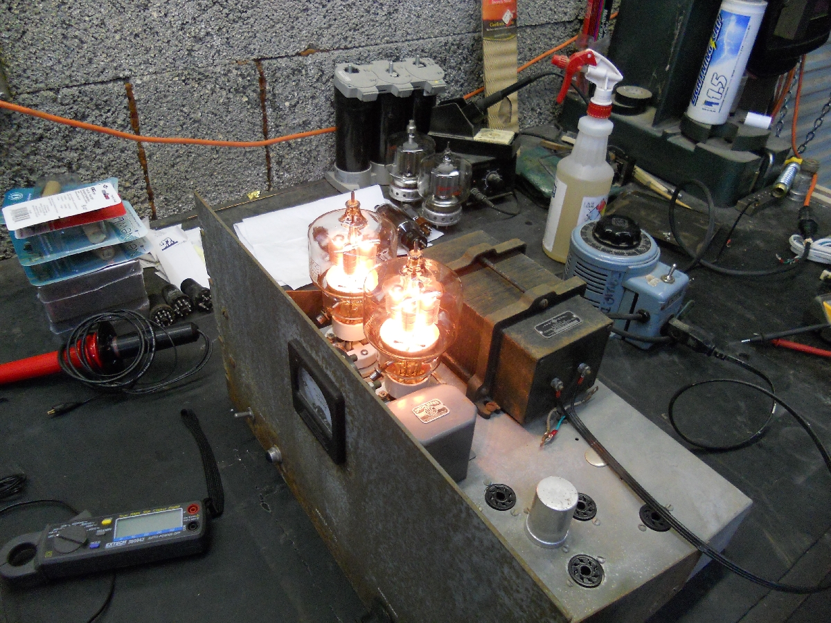
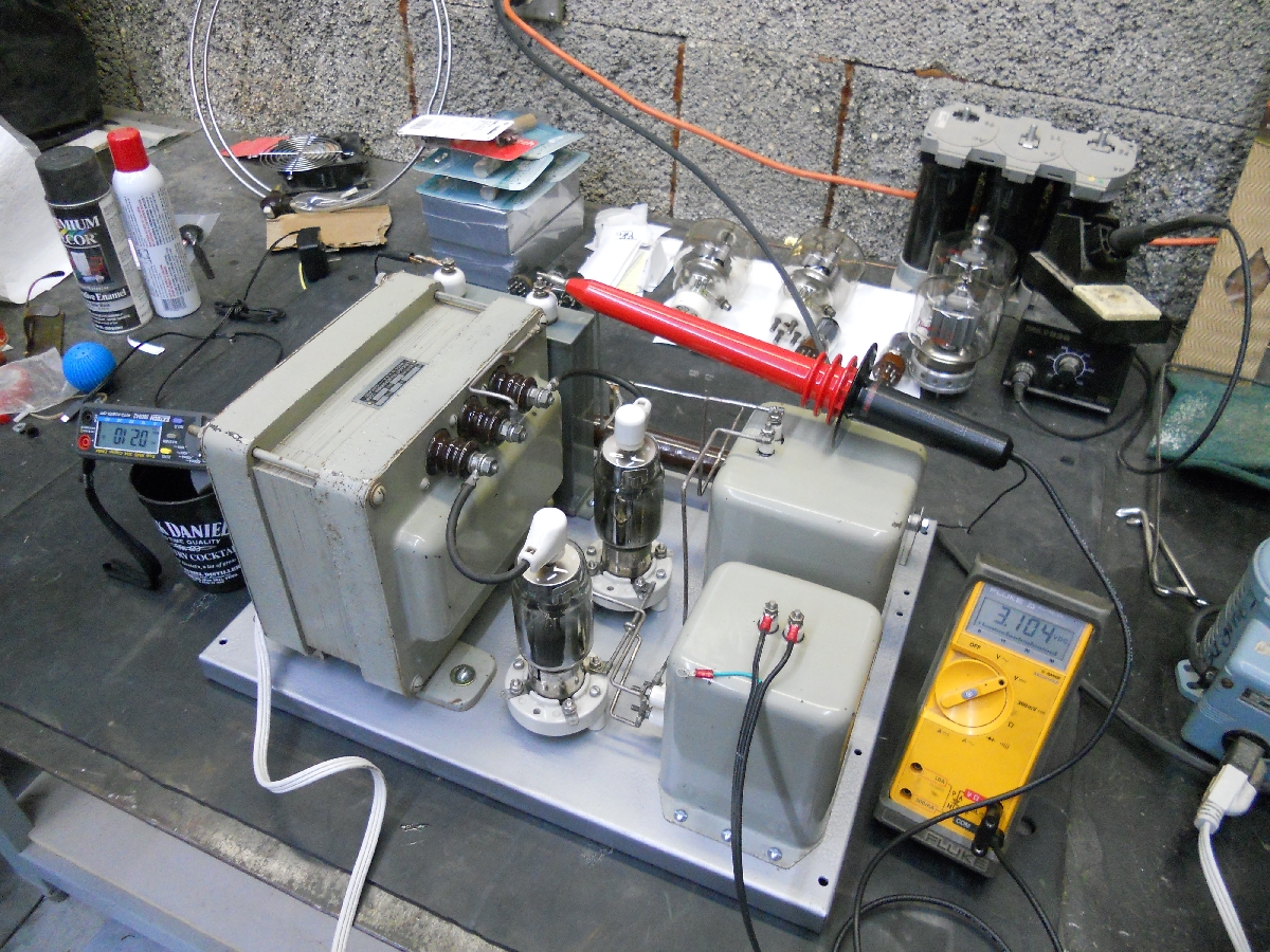
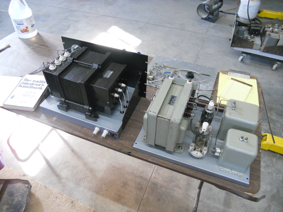
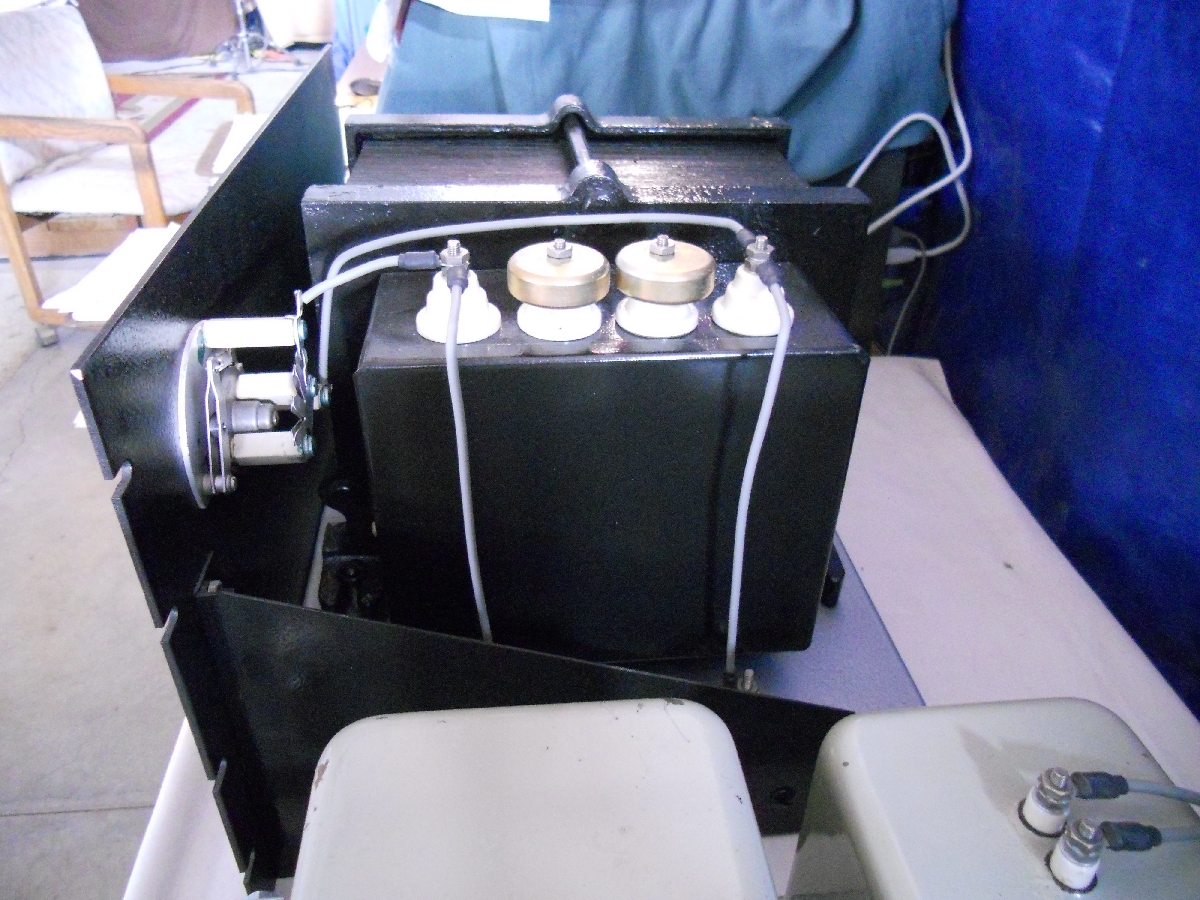
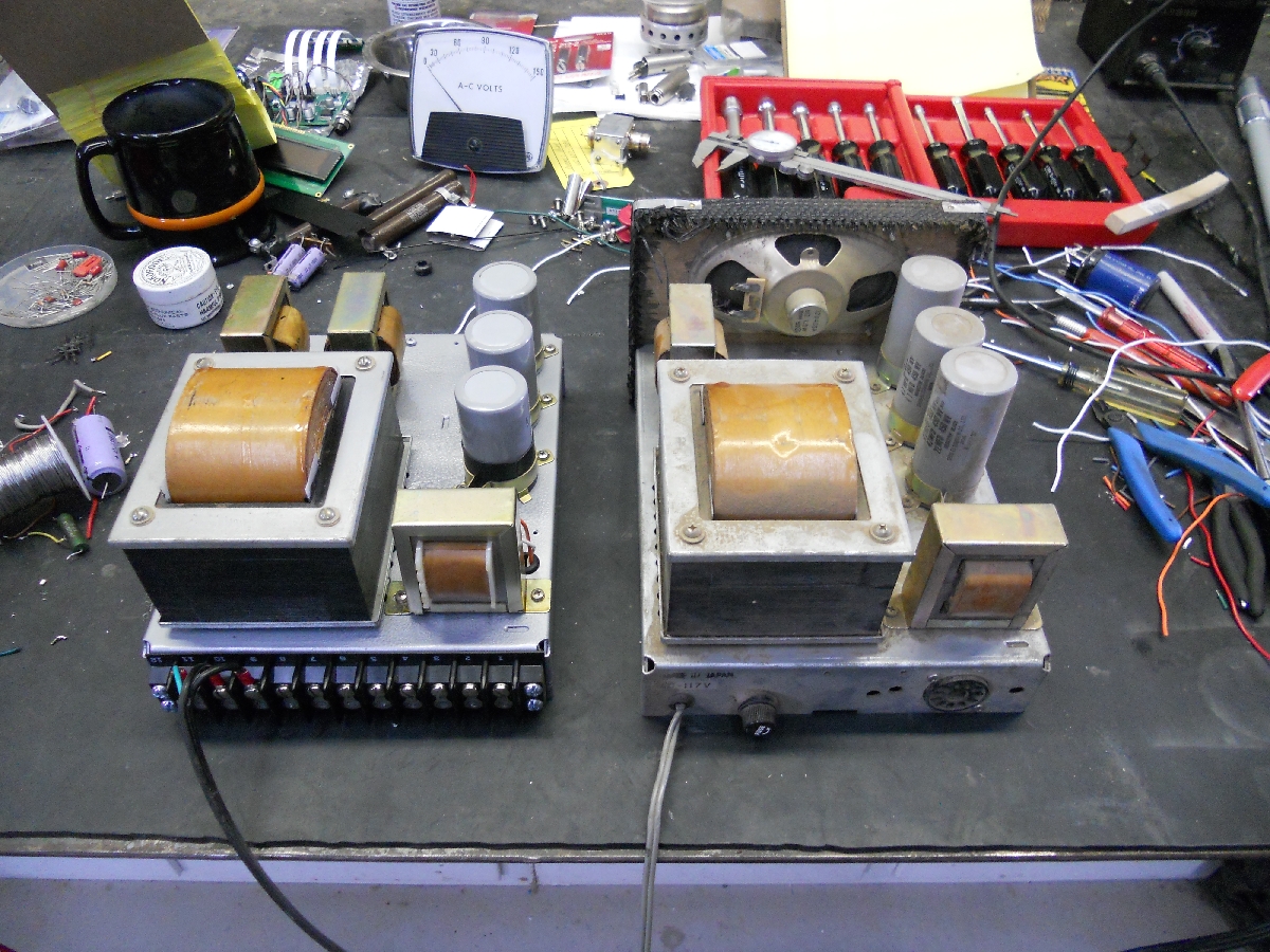
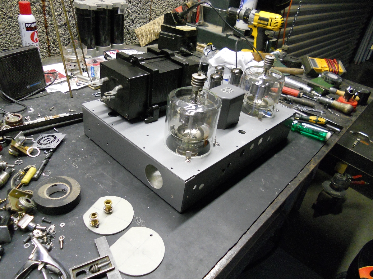
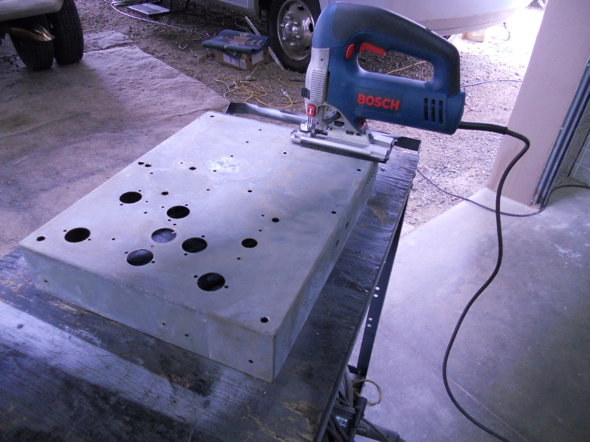
With that kind of info (and where are you going to find genuine "Bud Radio" steel chassis), how can you not do SOMETHING cool with this? I pulled the modulator's rusty, dusty chassis out, cleaned it up a little, and presto! After a 24 hour warm up on the 3B28's.... 3kv under load; the supply was still good. So I cleaned it up, leaving all the original components intact and adding just a few mods along with rewiring. Then I took the covers of the ends of the monster modulation transformer for an inspection. Having built transformers in my younger years, I noticed what appeared to me as a superb job on the rewind. A turns ratio and hi-pot check revealed it to be in very good condition, so it too got cleaned up. |
|||||
mod 6L6 pwr supp
1.01 MB |
modified 6L6 supply
951 KB |
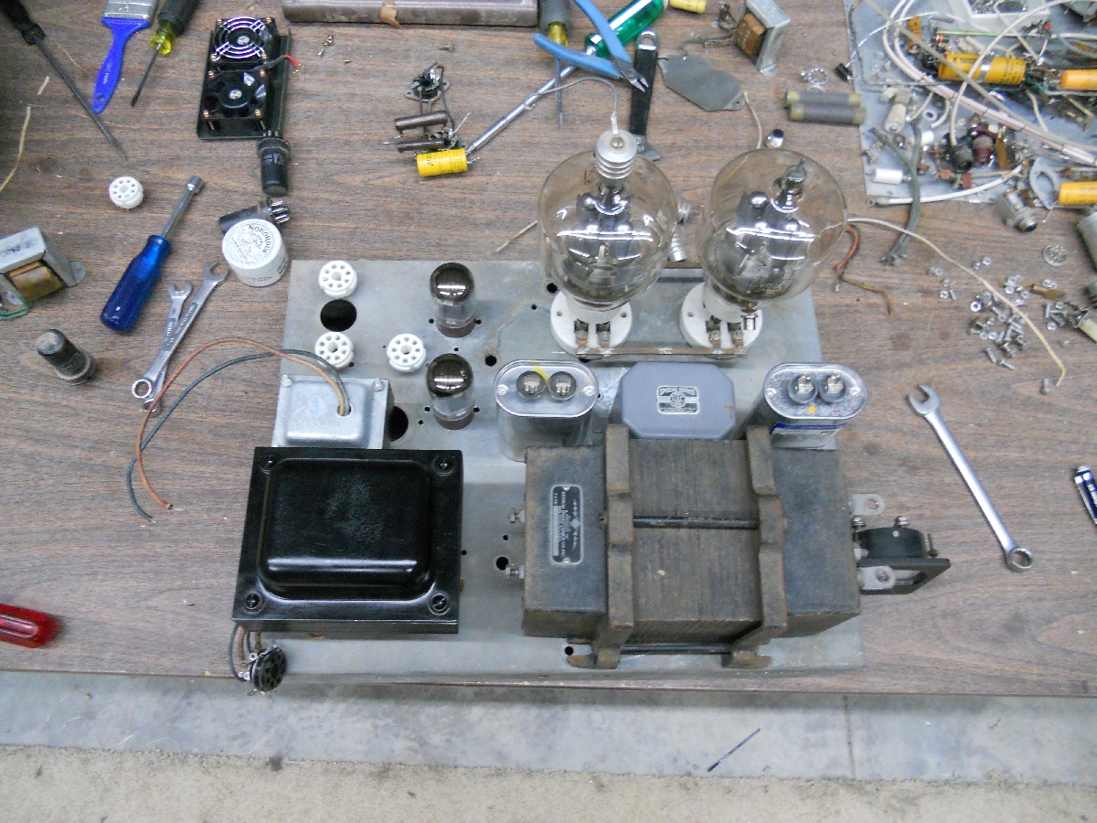
new mod layout
916 KB |
new layout-02
1.03 MB |
new layout-03
989.27 KB |
new layout-04
921.76 KB |
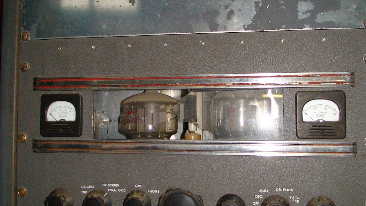
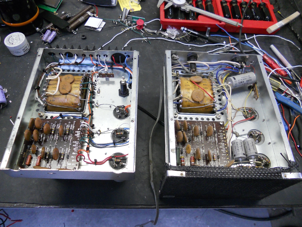
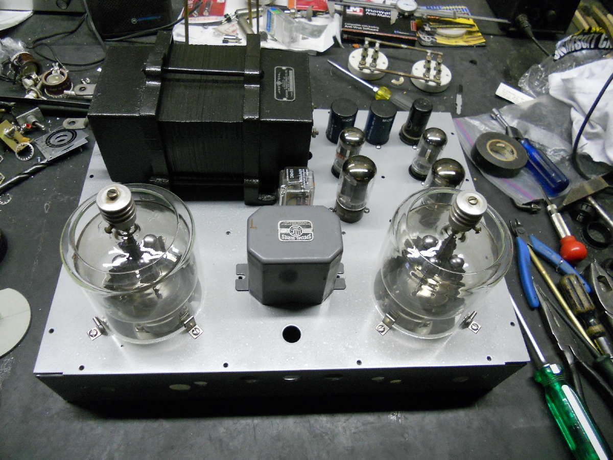
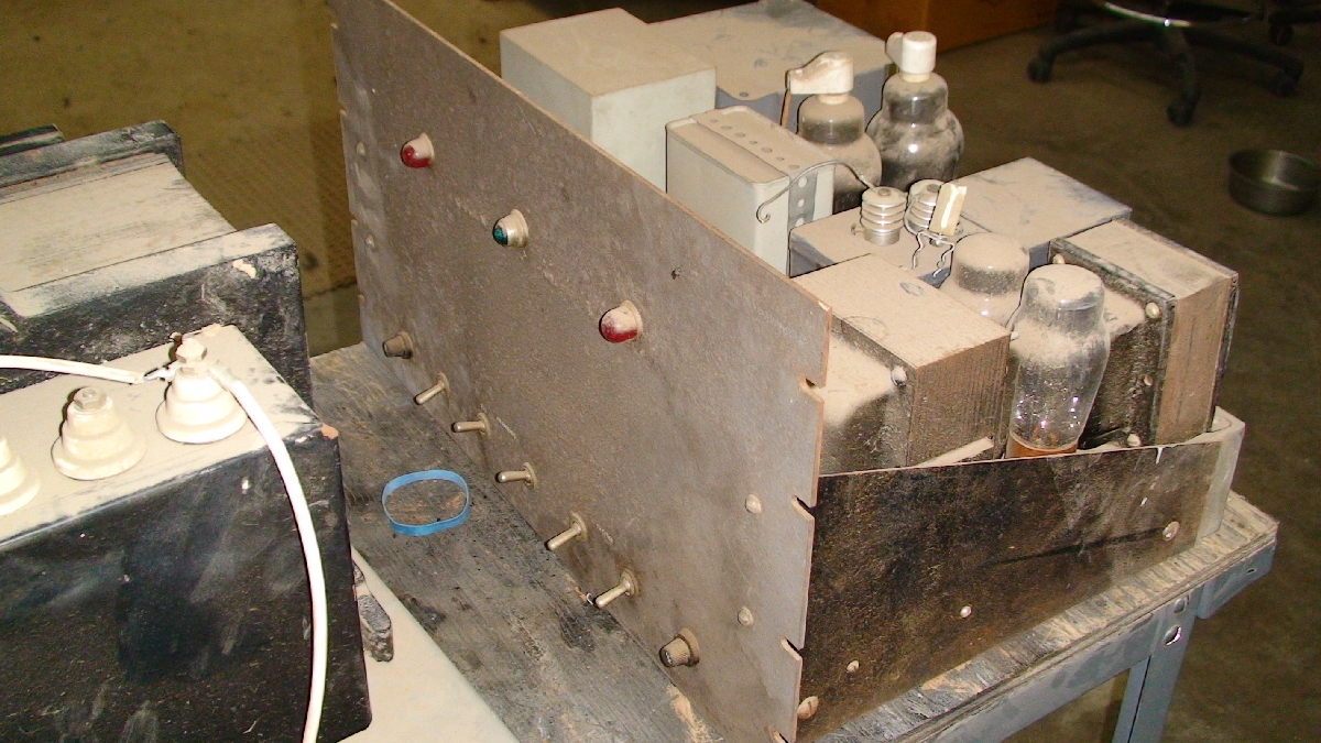
Now here's where the actual modulation deck came into the picture. The original chassis had the 304tl's placed on top of the Bud chassis with a "blow dryer" type fan pointed at them to keep them cool. Pretty lame design, but it must have worked very well. I checked the 60A / 5V filament transformer, and it too was OK. Hmmm. The chassis vas very corroded, tube sockets shot; etc. It just so happened that as I while inspecting the 6L6 drive circuit and drawing a "mediocre" schematic of the modulator, something struck me as "I've seen this before". I went to my cabinet and pulled out an old, tattered 1950 ARRL Handbook given to me by a SK's son several years back, and there, on page 292, was the exact schematic diagram of the chassis I was looking at! Wow! I was looking at a project I wished I could have afforded to build when I was a young lad! It was then that I began thinking: "I've got to do something with all this stuff... if anything else, to build a 1950's, era-correct project". |
|||||
new layout-05
1003 KB |
new layout-06
787 KB |
new layout-07
850 KB |
new layout-08
910 KB |
new layout-09
948 KB |
new layout-10
923 KB |
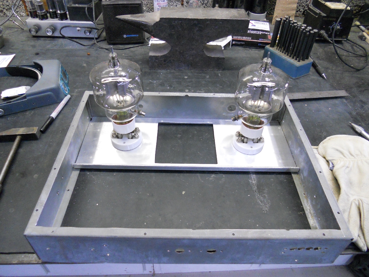
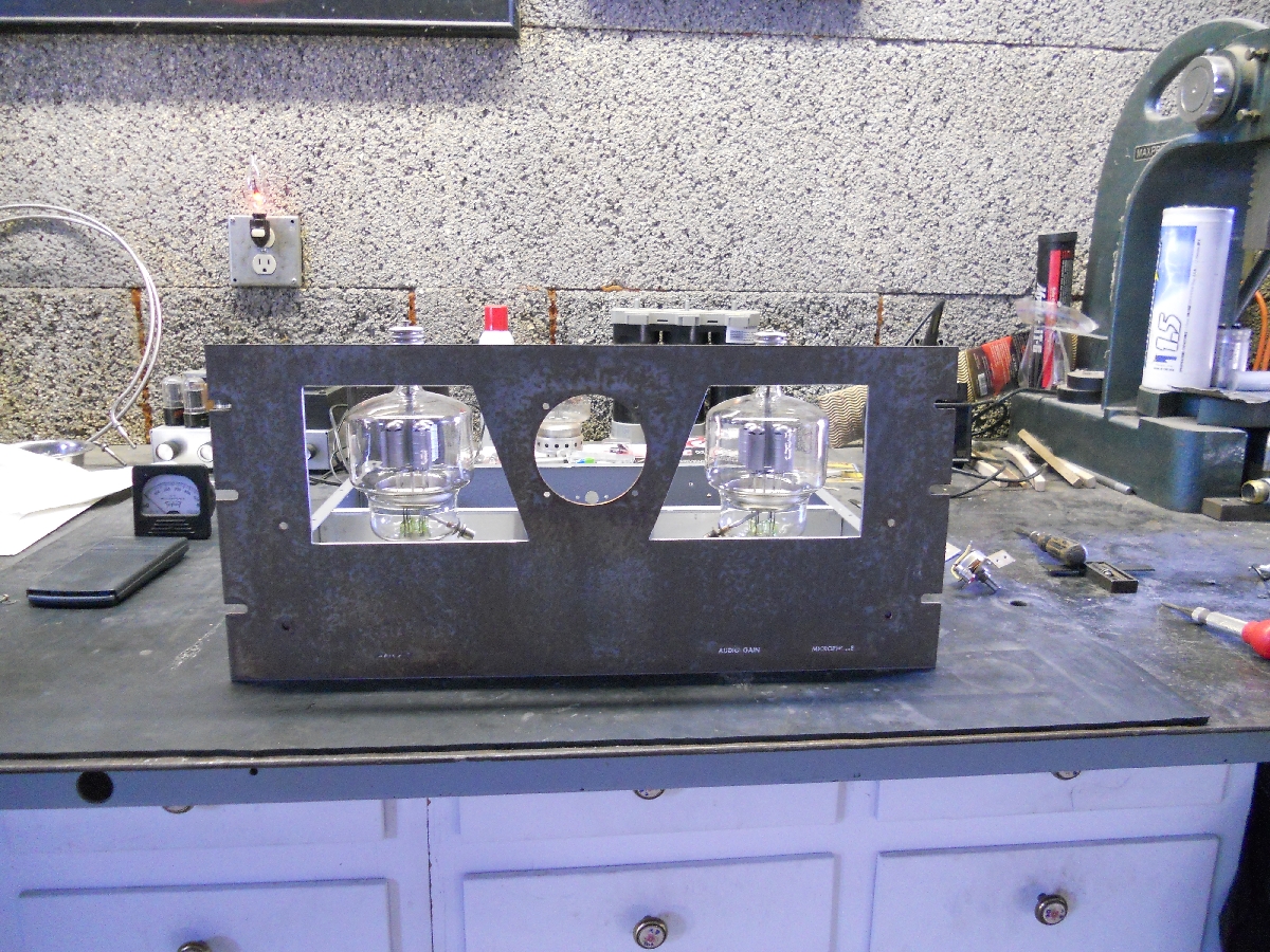
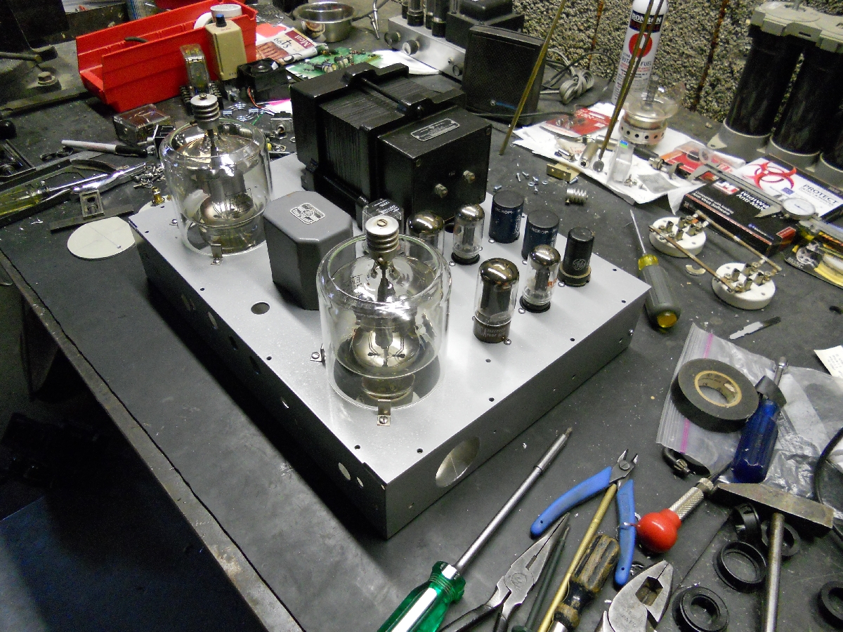
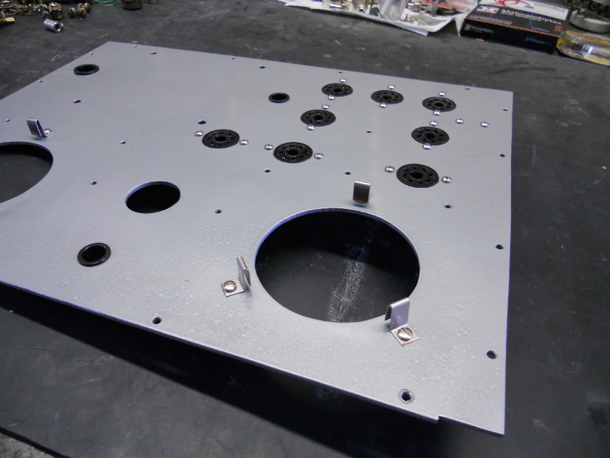
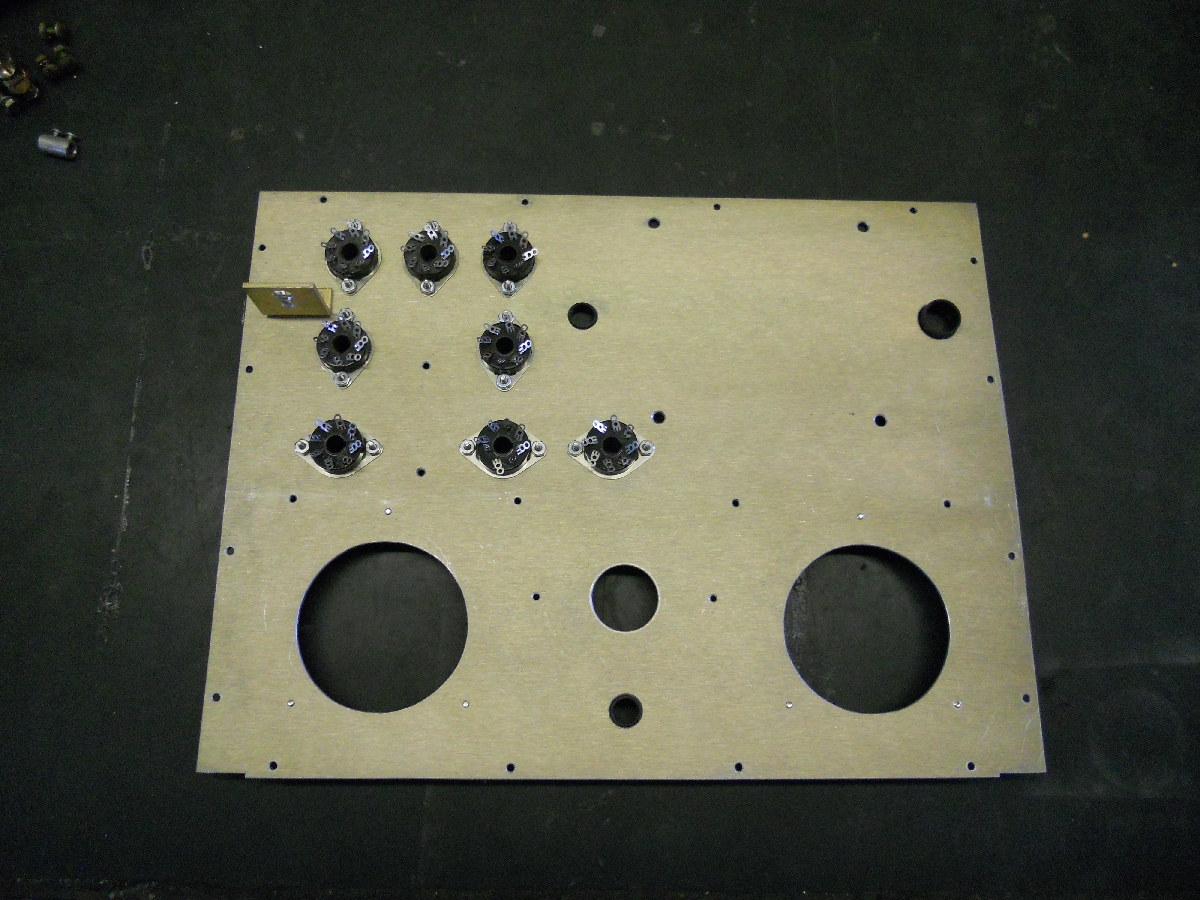
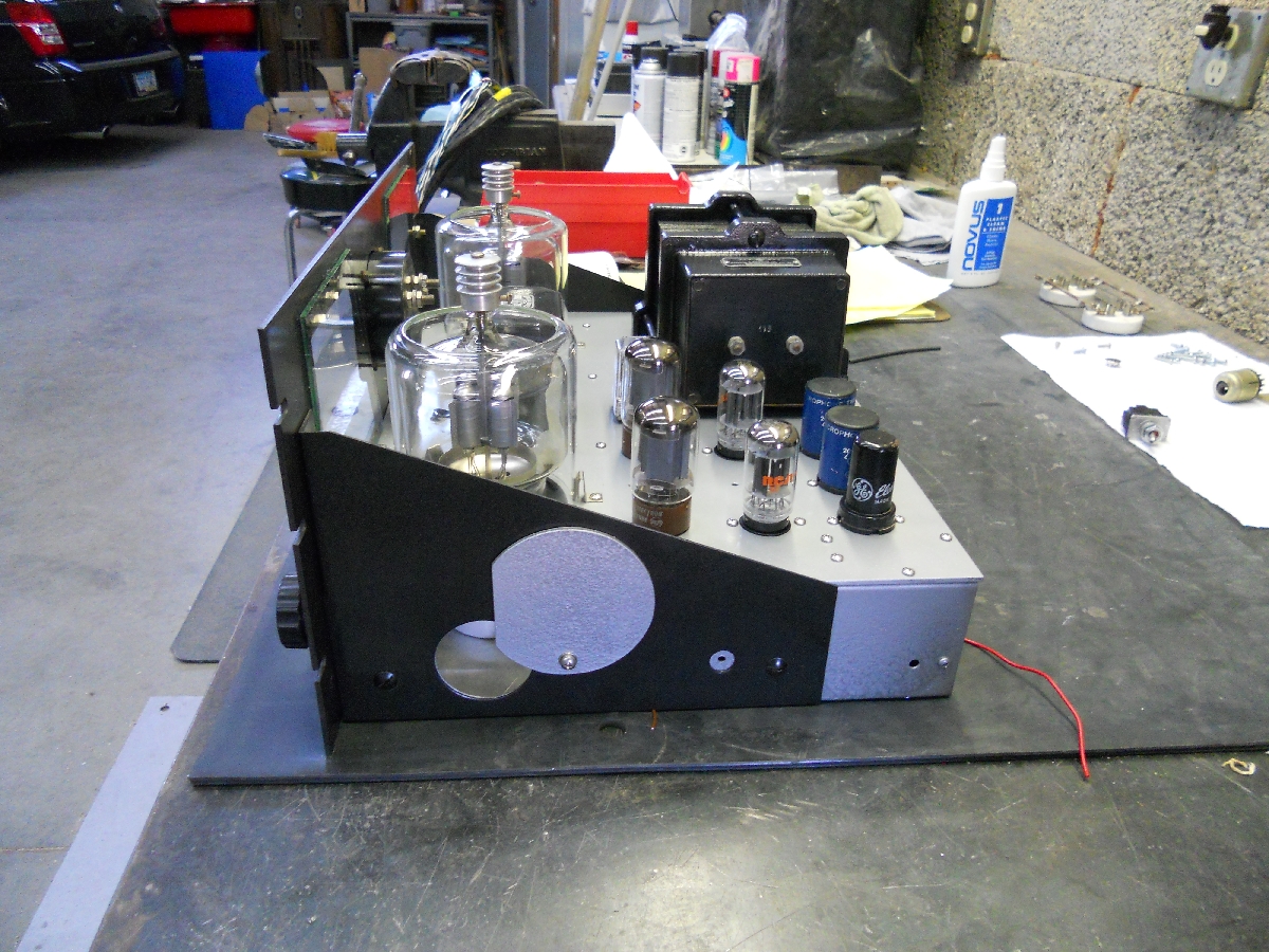
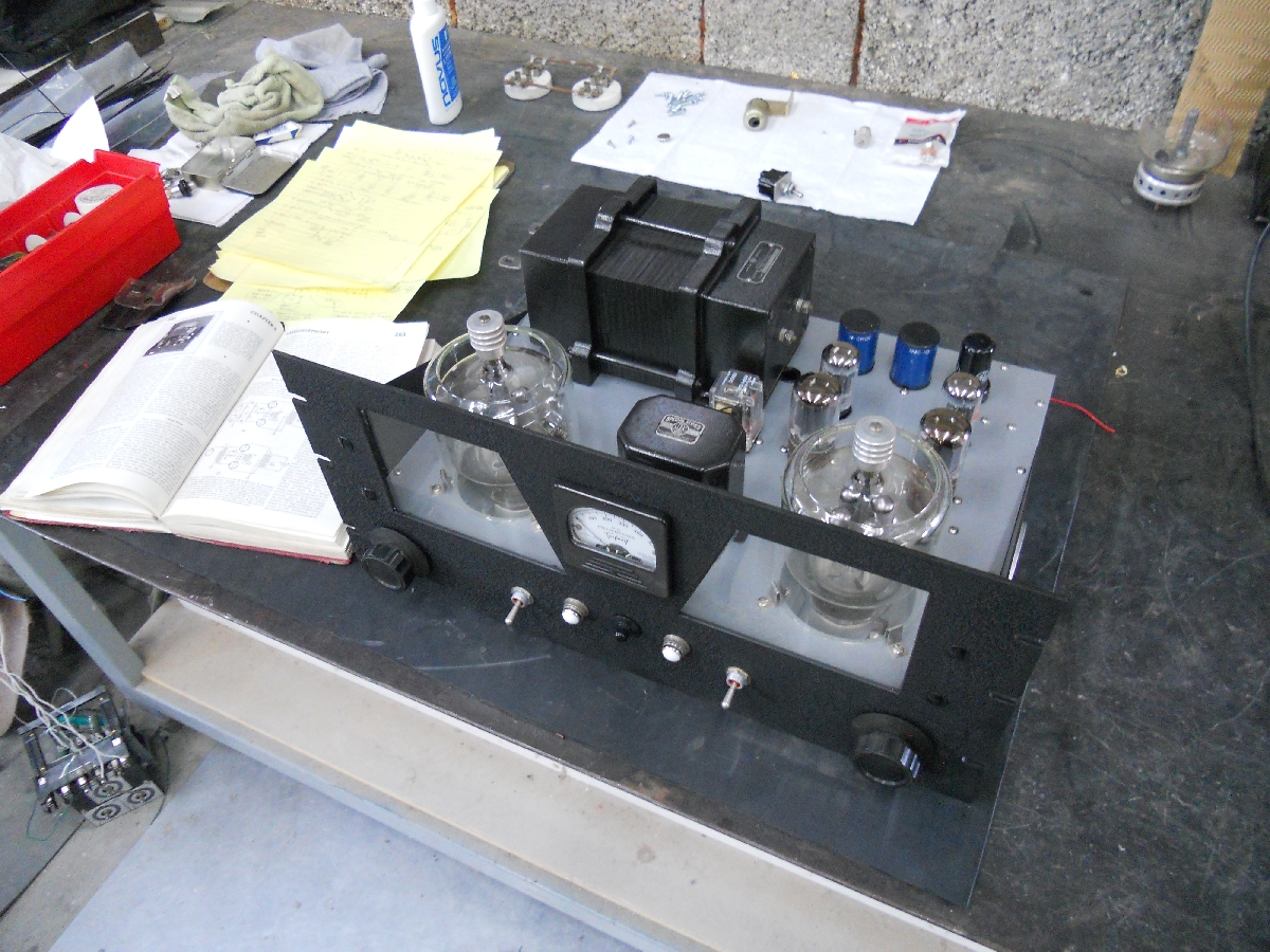
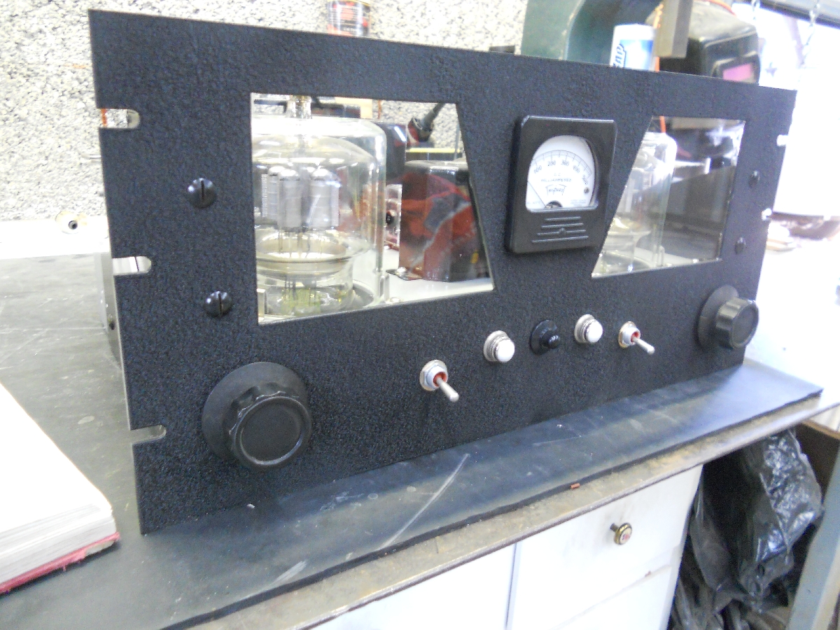
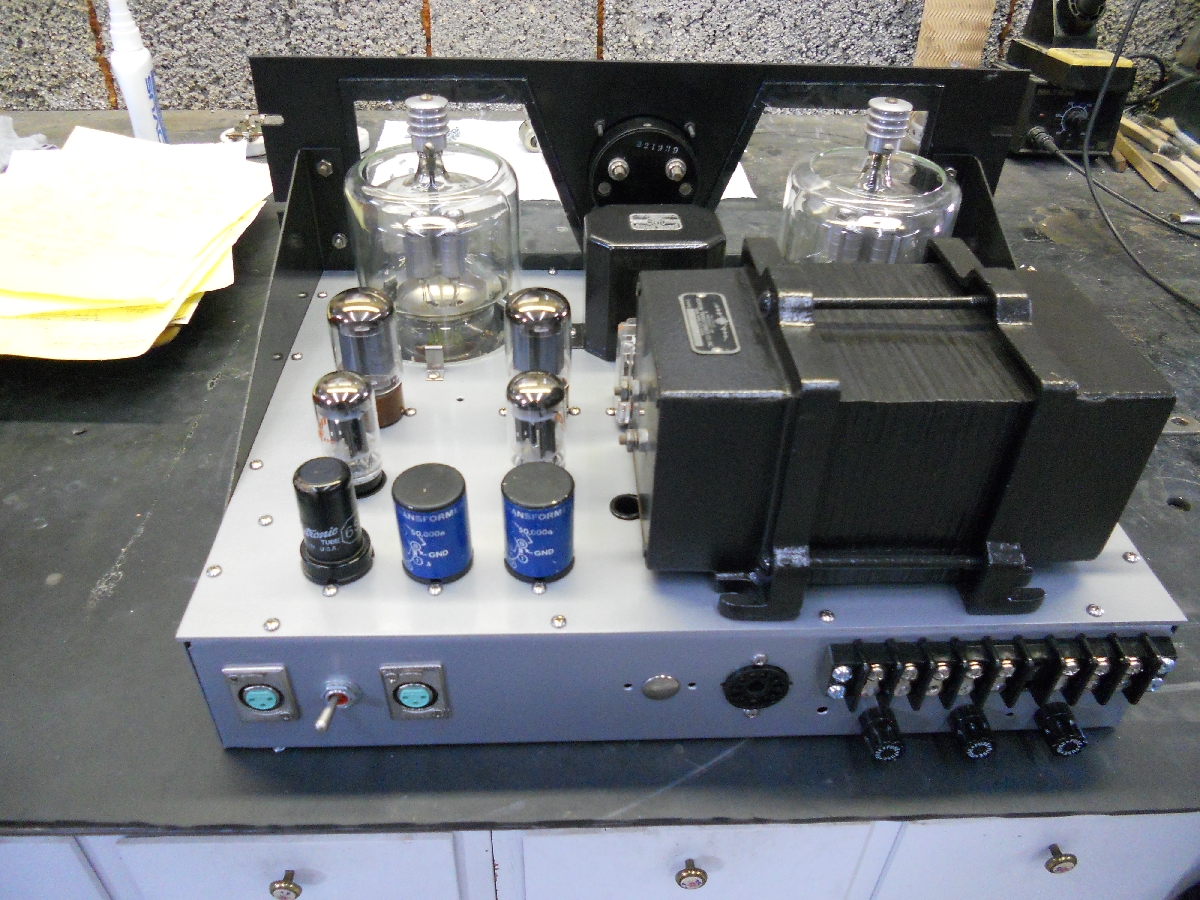
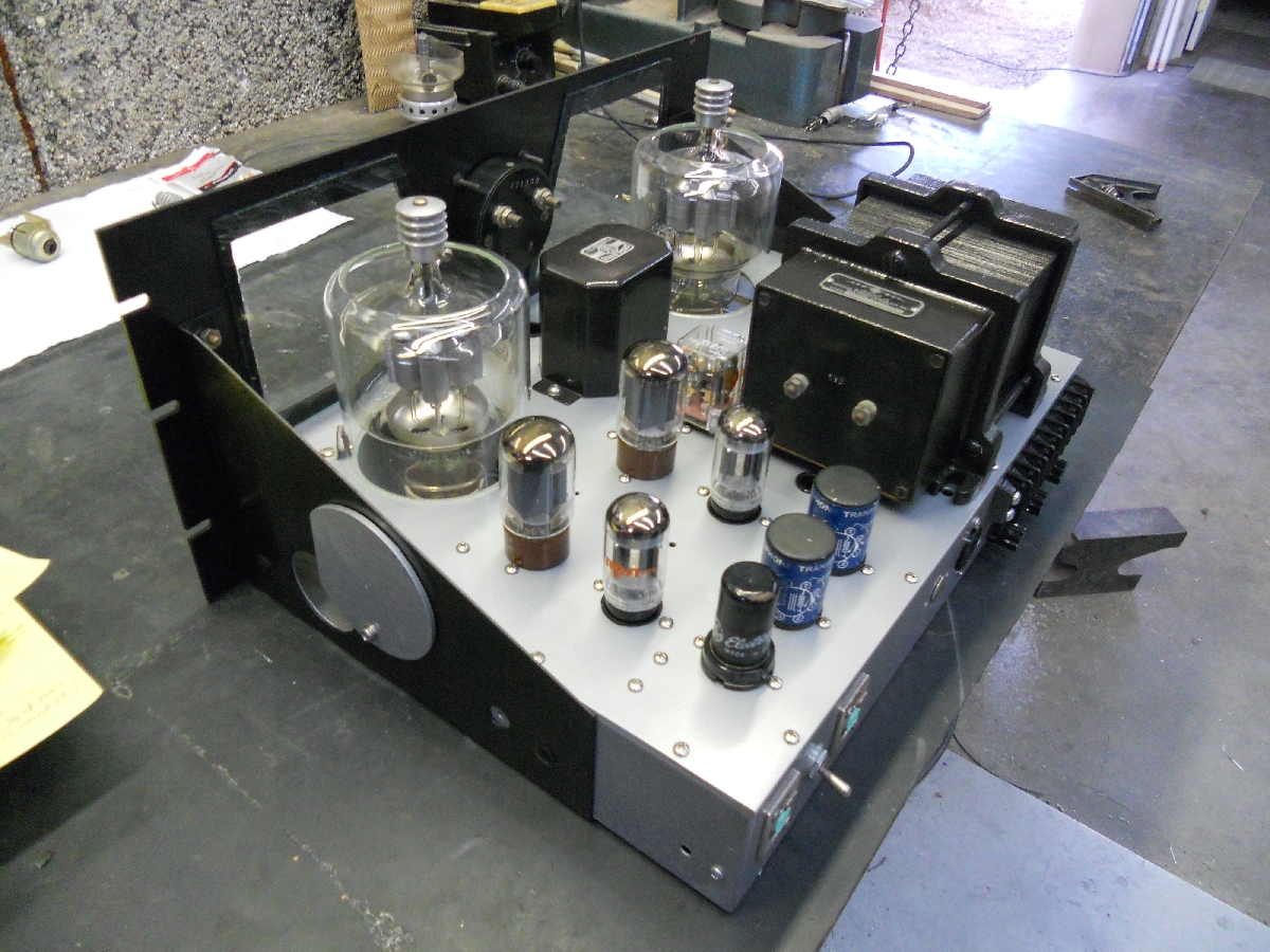
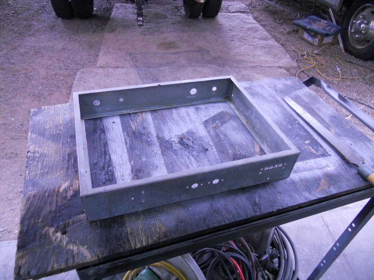
I began asking fellow hams on the 40 and 75 meter AM "window" their opinions on "how to". I incorporated their experiences into the "resurrection", if you will, of the modulator deck. It appears that the most important thing is to keep the 304tl pins cool, followed by the glass. From what I have gathered so far, Eimac recommends about 15CFM or so per tube, with ample air blowing across the envelopes. I wanted to keep a short profile on the chassis, so I opted to place the tubes in a chamber. Air is sucked in from the bottom center using a 100CFM box fan and is redirected through glass chimneys past the tubes. I understand that this is considered "not conventional" for 304tl's, but my buddy Chris (aka Dr. Spark) has a chimney around his single 304th Tesla coil (20 inch+ sparks) and his use of a chimney allowed him to essentially double the original input power compared to just blowing a breeze across the glass. So I'm hoping this is a good idea. To help cool off the 304tl pins and reduce the air through the chimneys, I punched a 2 inch hole on either side of the chassis and installed "adjustable" concentric baffles which seem to do an excellent job balancing the air flow as well. The modulator isn't wired yet, but I'm ready! |
|||||
new layout-11
847 KB |
new layout-12
927 KB |
new layout-13
922 KB |
old mod chassis-01
880 KB |
old mod chassis-02
948 KB |
Power Supply
662 KB |
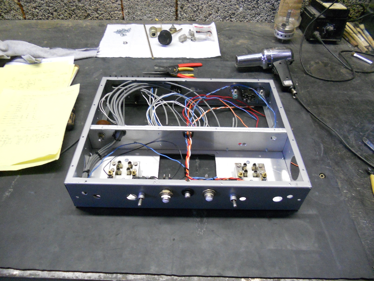
There is no room on the chassis for the 6L6 plate or the 304tl bias, so I modified an old Tempo One supply with a remote connector for that. Sorry about the long-winded explanation. I just thought you might like to know how I got from point A to B with a little Phoenix ham history thrown in. |
|||||
Power Supply-old
637 KB |
Pwr Supp-old-01
655 KB |
Pwr Supp-old-top
605 KB |
|||
73's for now Henry, KB7OCY |
|||||