WLW Period Photos 1926 - 1942
Return to Main WLW page
| These pictures date
from 1926 to 1942 showing WLW at the start of the transmitter and
antenna locations at Mason, Ohio. Other pictures are of Powell Crosley Jr., Joe Chambers, five young ladies on the catwalk of the new 500,000 Watt WLW transmitter, Crosley Square Crosley factory, Interior of the WLW transmitter building, modulation transformer installation, flat top and vertical antennas, substation, exterior of WLW and WSAI transmitter buildings, Crosley Radio Labs, Lowell Thomas, Red Barber, Crosley airplanes, etc. |
|||||
01.jpg
178.01 KB |
02.jpg
149.18 KB |
03.JPG
143.79 KB |
04.JPG
124.90 KB |
05.jpg
232.52 KB |
06.JPG
207.09 KB |
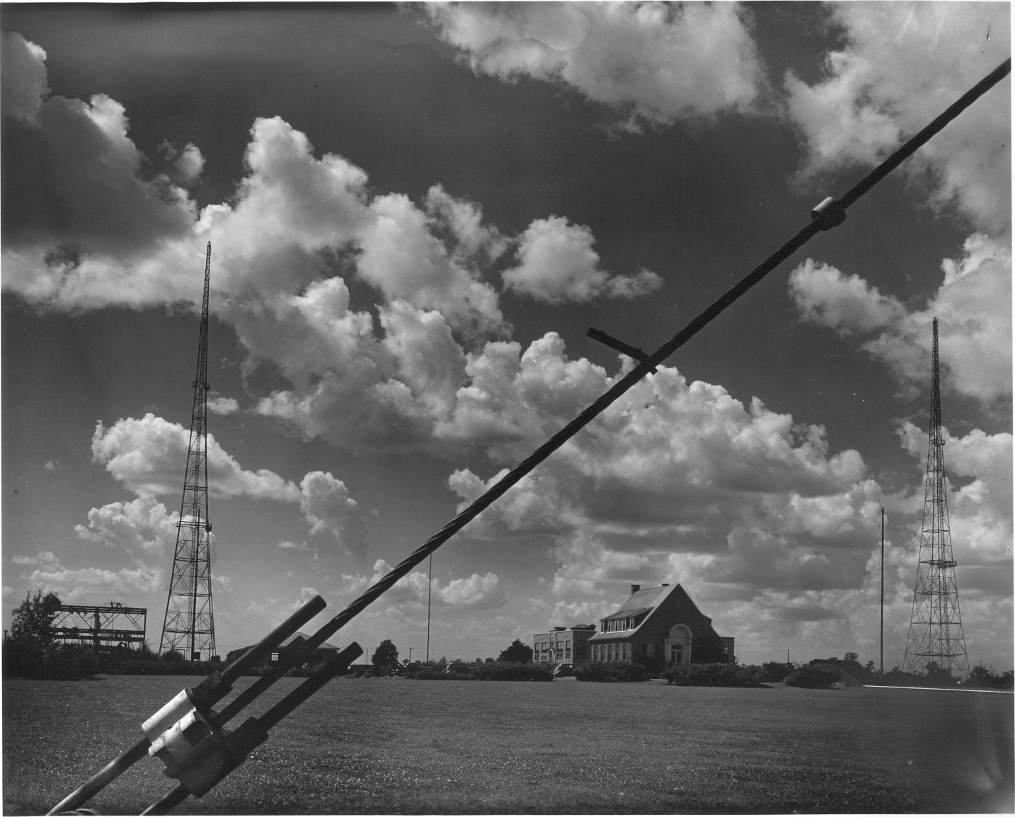
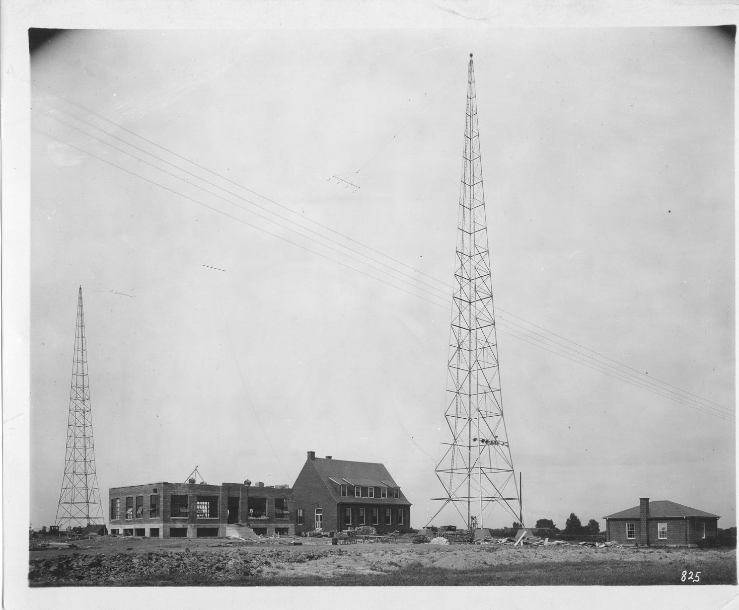
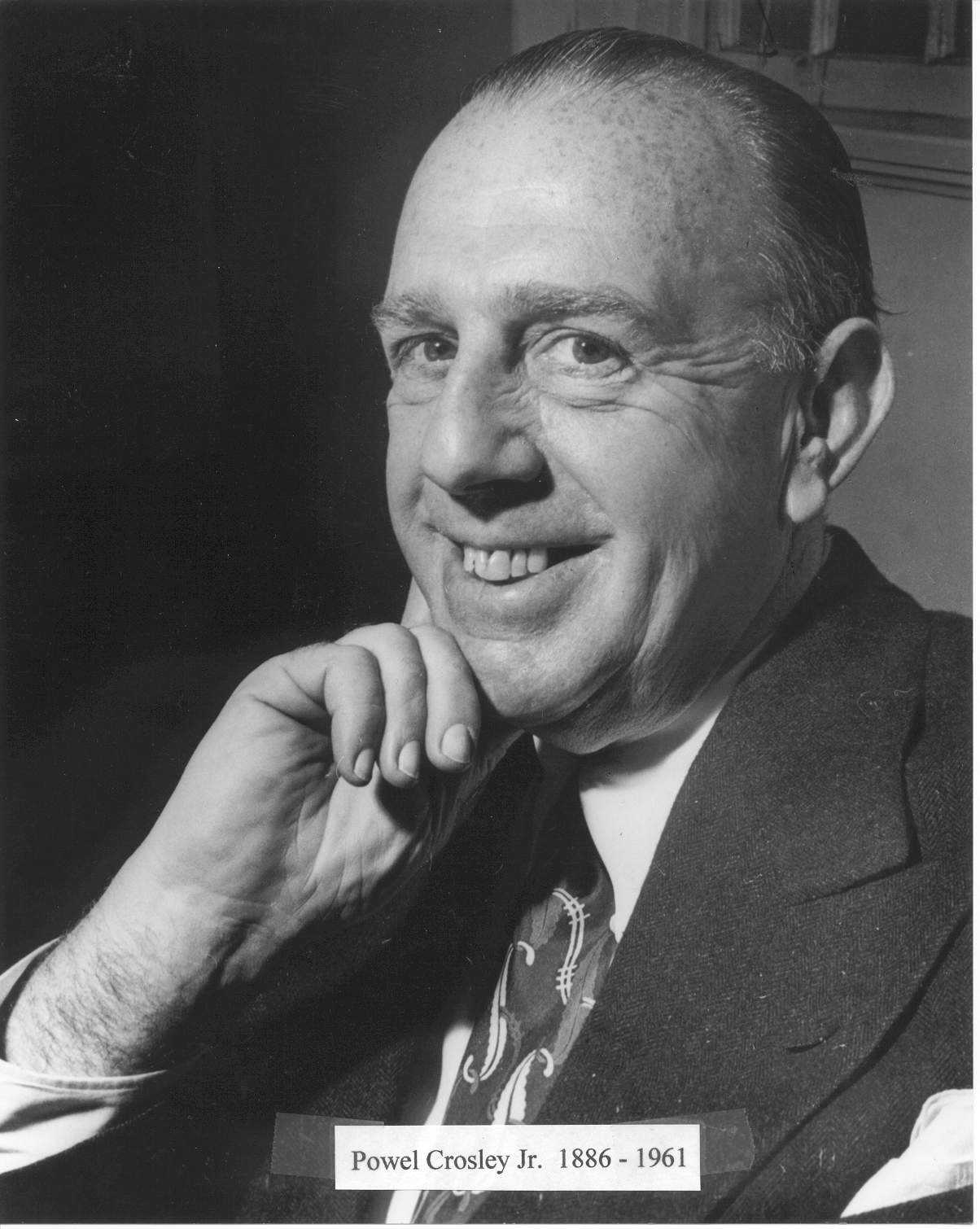
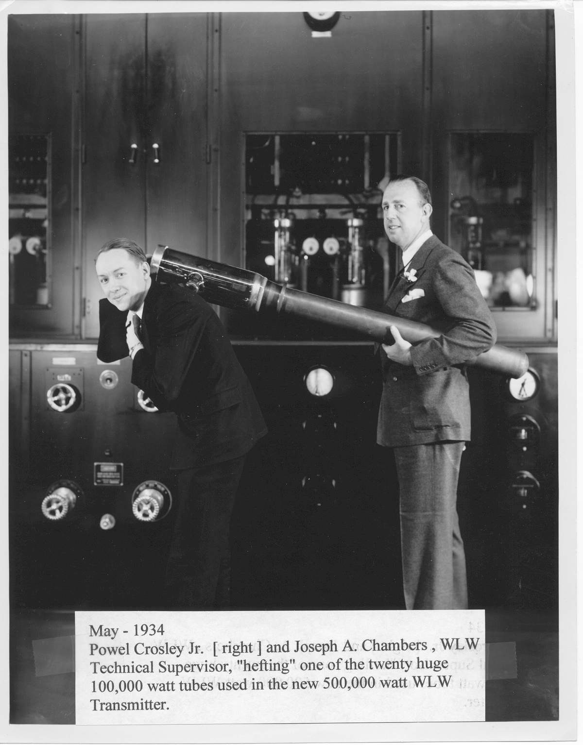
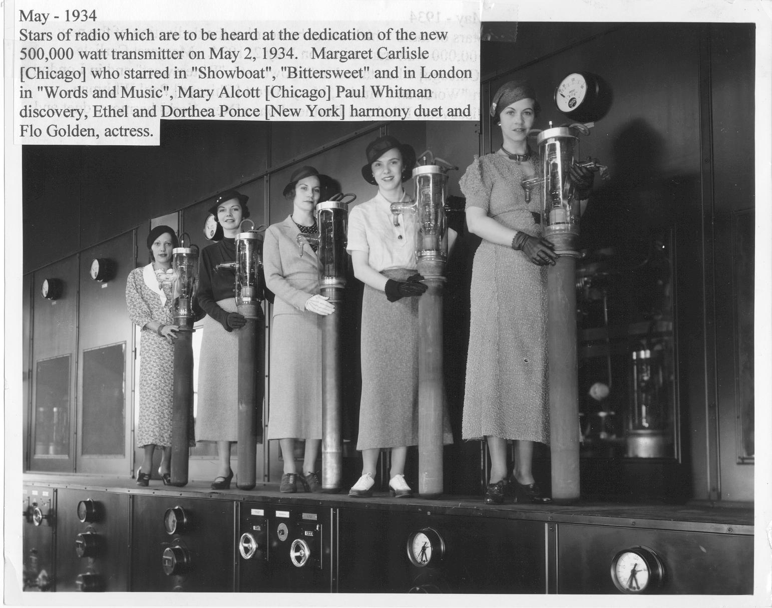
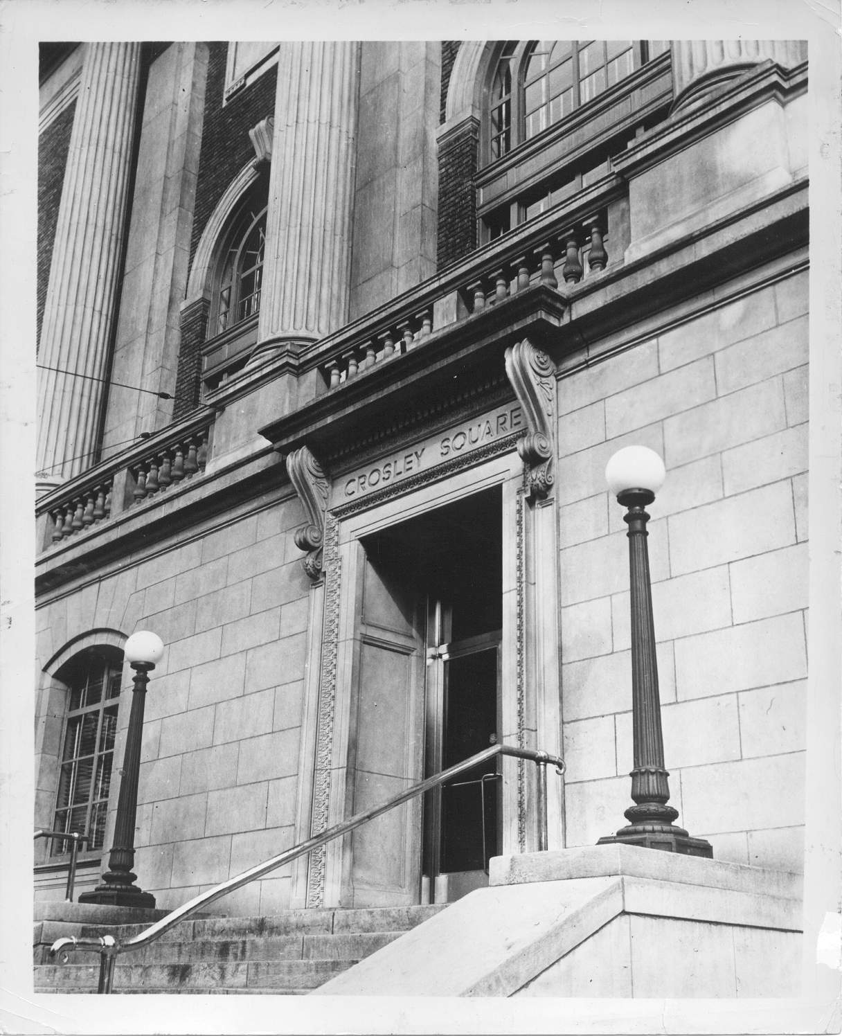
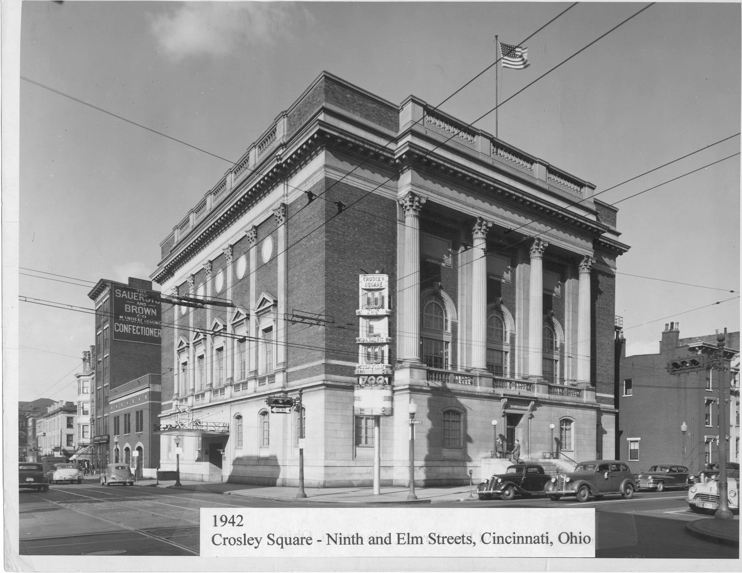
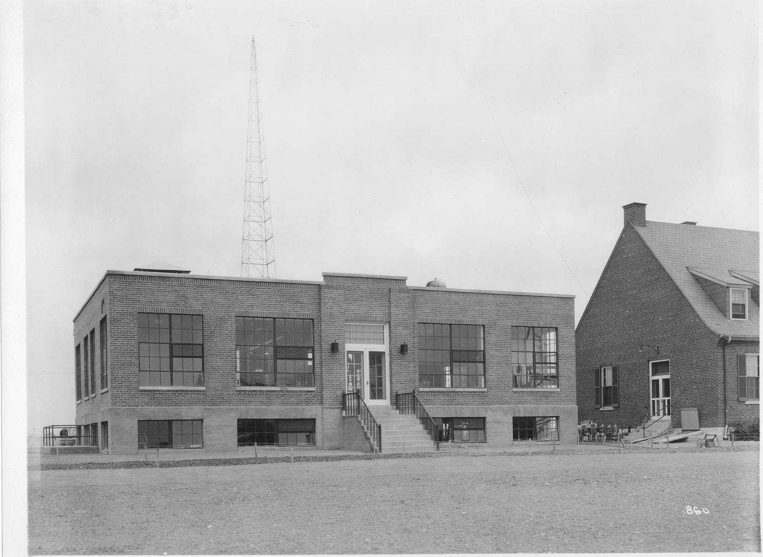
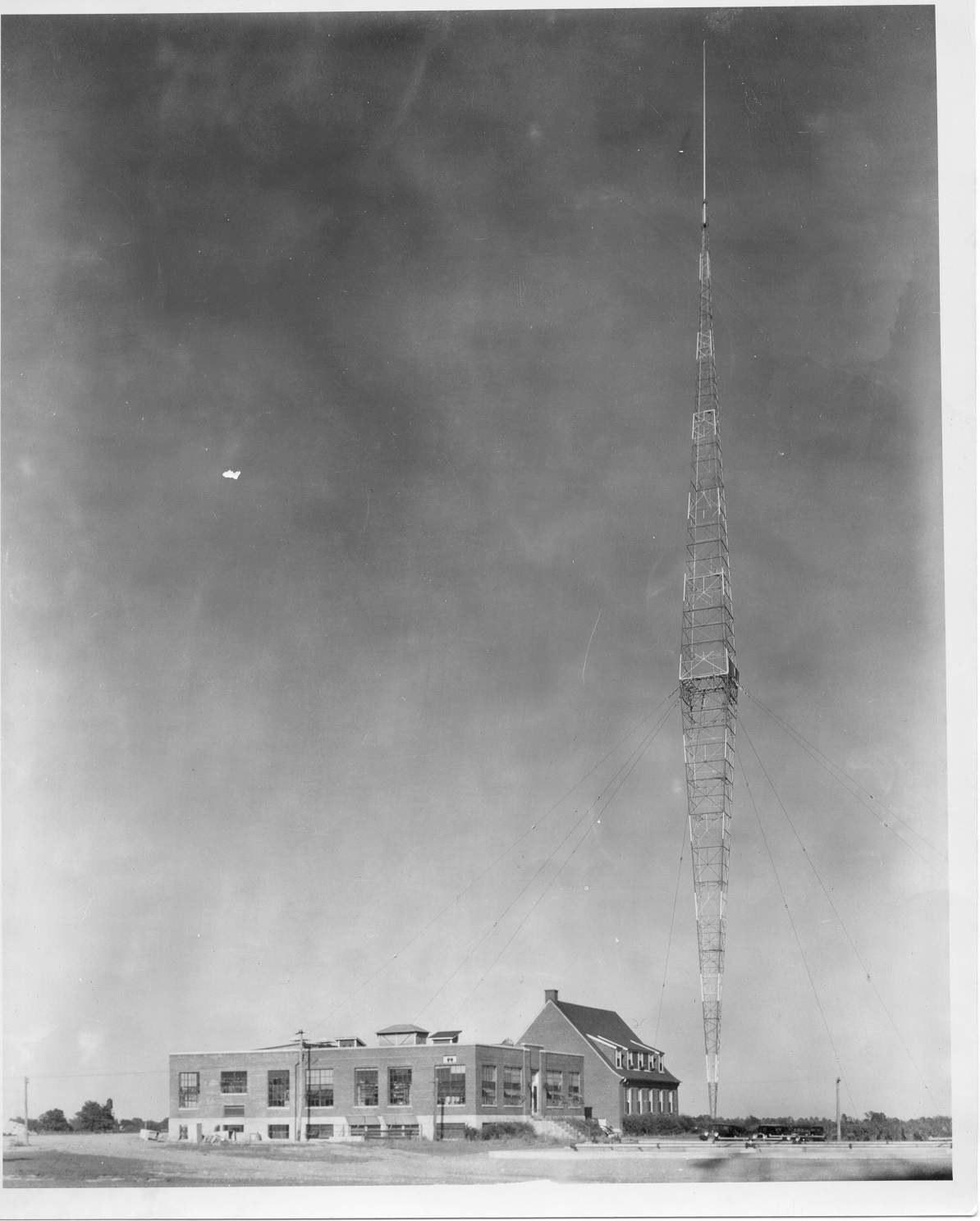
01. 1934 WLW transmitter Plant - showing one of the guy wire sockets in the foreground. This striking photograph frames the WLW transmitter site at Mason, Ohio, about 25 miles north of Cincinnati. Shown looking across a guy cable of the giant Blaw-Knox inverted pyramid, 831 foot high tower. The building in the foreground originally contained the WSAI station transmitter. The building in the background is actually larger and houses the 500,000 Watt transmitter of WLW. At the far left can be seen the electric power substation. The two 300 foot towers support a wire flat-top “T” antenna which can be switched into service from the main transmitter building 02. 1927 WSAI transmitter building and antenna. The WLW 50,000 Watt transmitter building is being built. The new WLW transmitter building under construction along side the WASI transmitter building at Mason, Ohio. This newly constructed building will house the new Western Electric 7A 50,000 Watt transmitter. Two 300 foot towers support a wire “T” antenna over the WSAI building. These two towers were subsequently moved about 300 feet to the west (to the left in this photograph) over a yet to be constructed coupling house. The footers of this tower in front of the WSAI house can be seen today. The buildings seen here are standing today. The building to the right is a garage. 03. Powell Crosley Jr. 1886-1961 04. May 1934 Powell Crosley Jr. (right) and Joseph A. Chambers , WLW Technical Supervisor, “hefting” one of the twenty huge 100,000 Watt tubes used in the new 500,000 Watt WLW transmitter. 05. These five stars of radio are to be hard on the dedication broadcast of the new 500,000 Watt transmitter on May 2, 1934. They posed for the camera while standing on the “catwalk” of the 54 foot 500,000 Watt amplifier panel. Each is holding one of the twenty giant 100,000 Watt tubes used in the transmitter. The tubes cost more than $1,000 each. Left to right are Margaret Carlisle (Chicago) who starred in “Showboat”, “Bittersweet” and in London in “Words and Music”; Mary Alcott (Chicago) Paul Whitman discovery; Ethel and Dorthea Ponce (New York) harmony duet; and Flo Golden, actress. 06. 1942 Crosley Square, Ninth and Elm Streets, Cincinnati, Ohio |
|||||
07.jpg
230.42 KB |
08.jpg
150.55 KB |
09.jpg
215.79 KB |
10.jpg
218.99 KB |
11.jpg
193.11 KB |
12.JPG
175.72 KB |
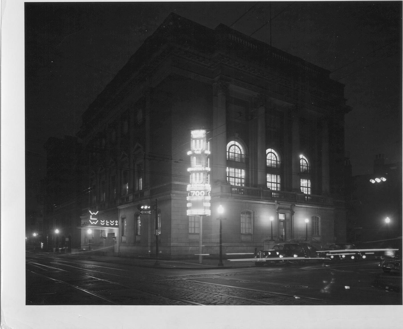
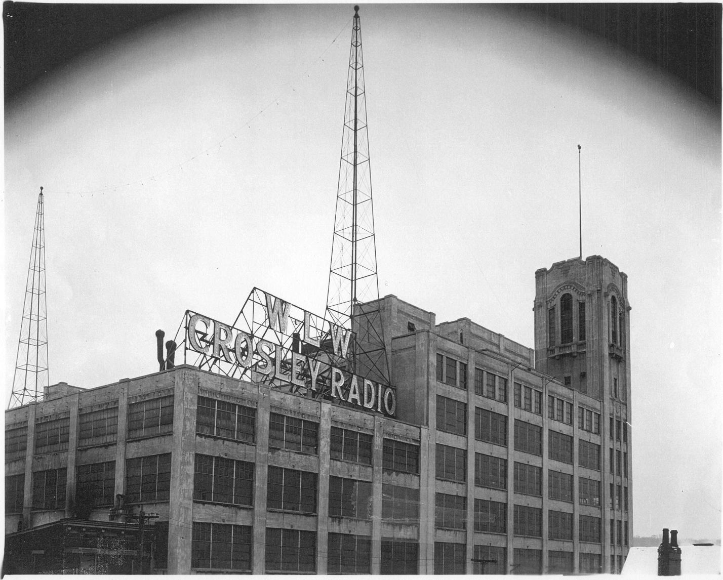
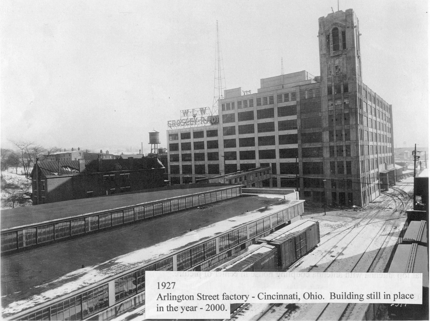
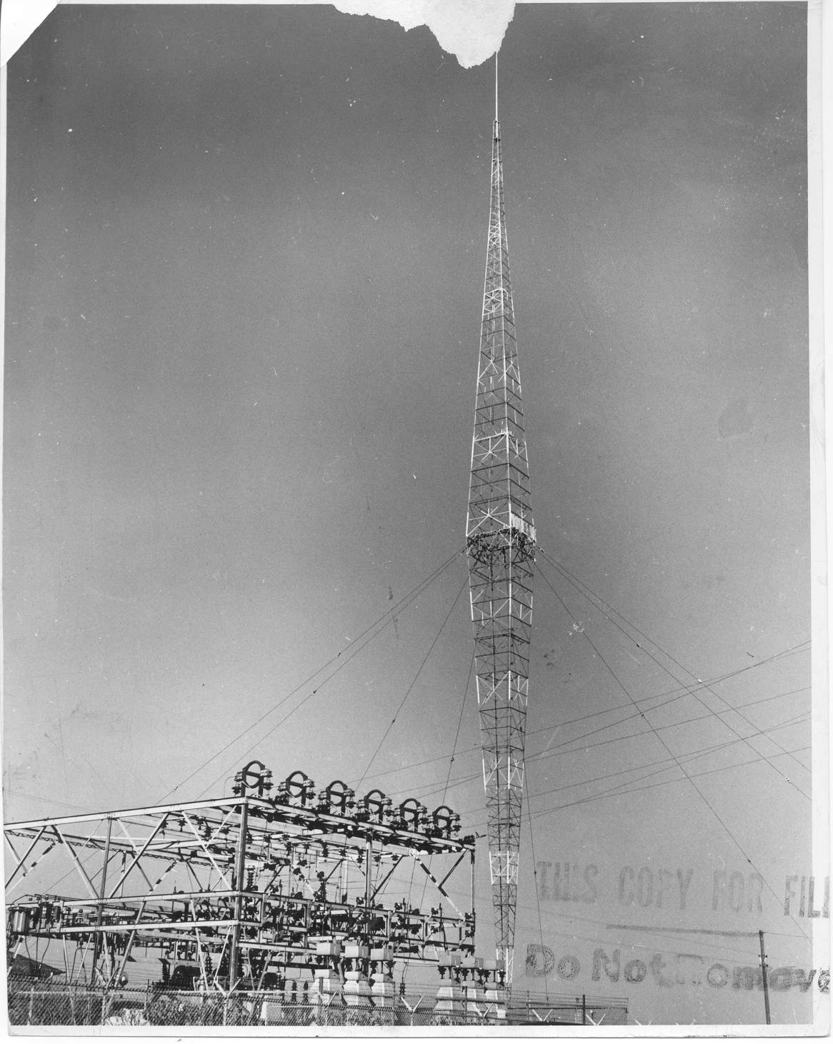
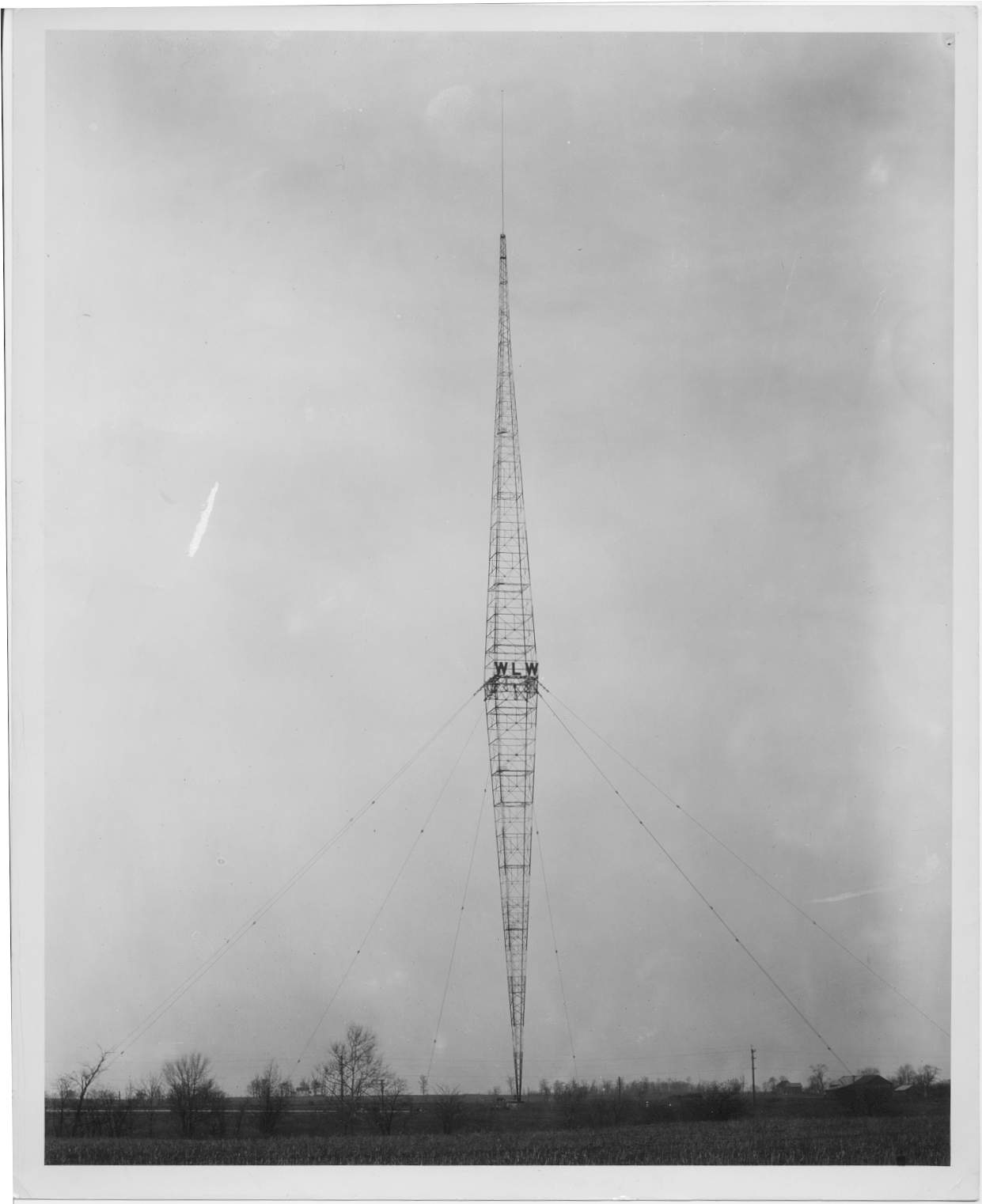
07. 1942 Crosley Square, Ninth and Elm Streets, Cincinnati, Ohio 08. 1942 Crosley Square, Ninth and Elm Streets, Cincinnati, Ohio. Night time - Note: the call letters WLWA and WLWO can be seen along with WLW. 09. 1927 Arlington Street factory, Cincinnati, Ohio. Building is still here today. 10. 1927 Arlington Street factory, Cincinnati, Ohio. Building is still here today 11. 1934 View of the WLW 500,000 Watt transmitter before the 862 tubes were installed. Joseph A. Chambers, Technical Supervisor. 12. 1935 WLW 831 foot vertical antenna and 33,000 Volt substation |
|||||
13.jpg
224.68 KB |
14.jpg
163.08 KB |
15.jpg
160.13 KB |
16.jpg
201.65 KB |
17.jpg
181.80 KB |
18.jpg
193.32 KB |
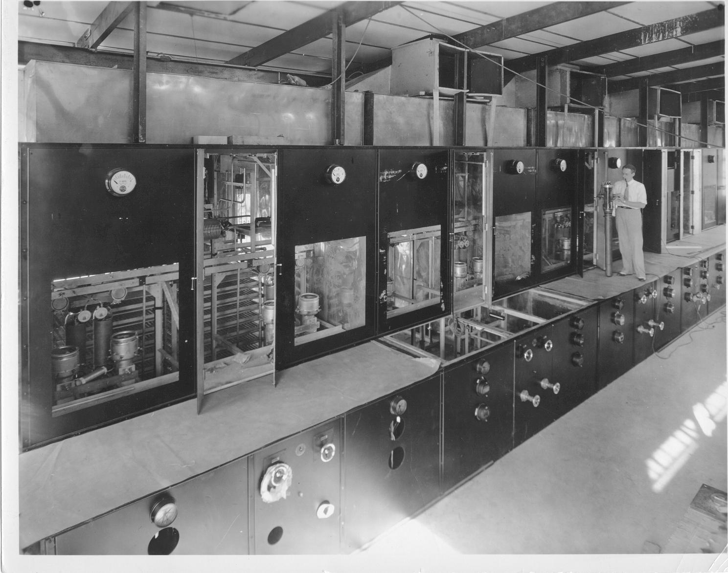
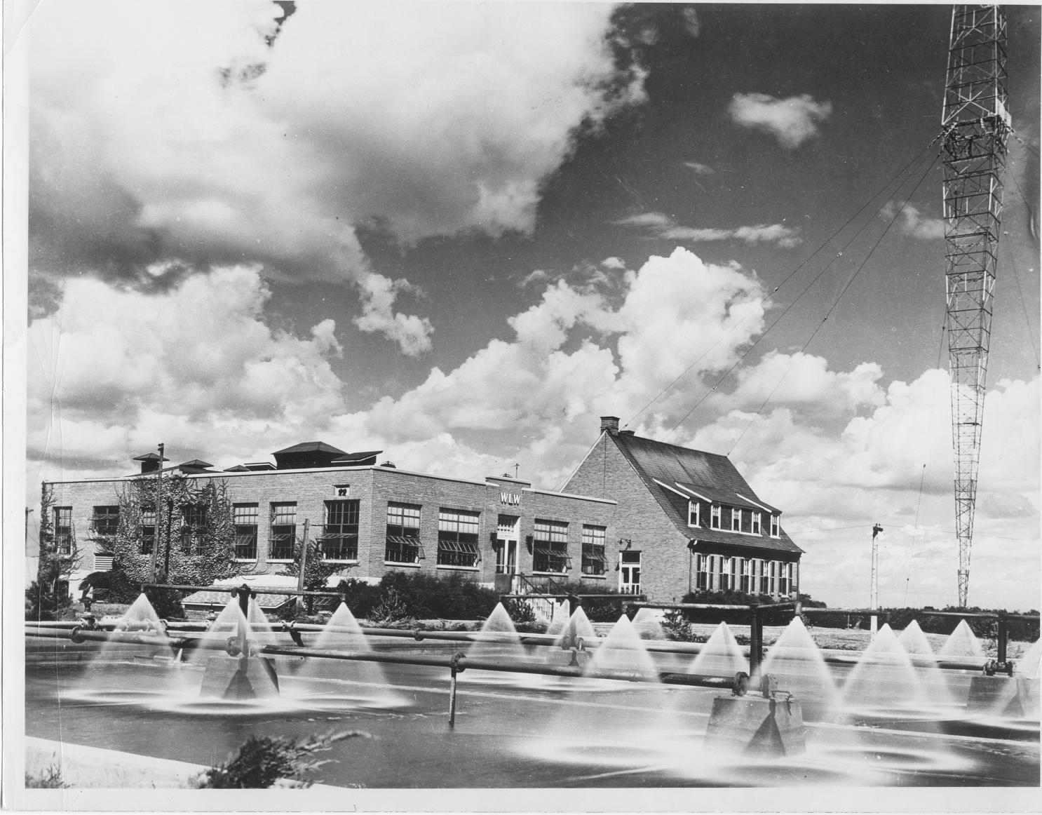
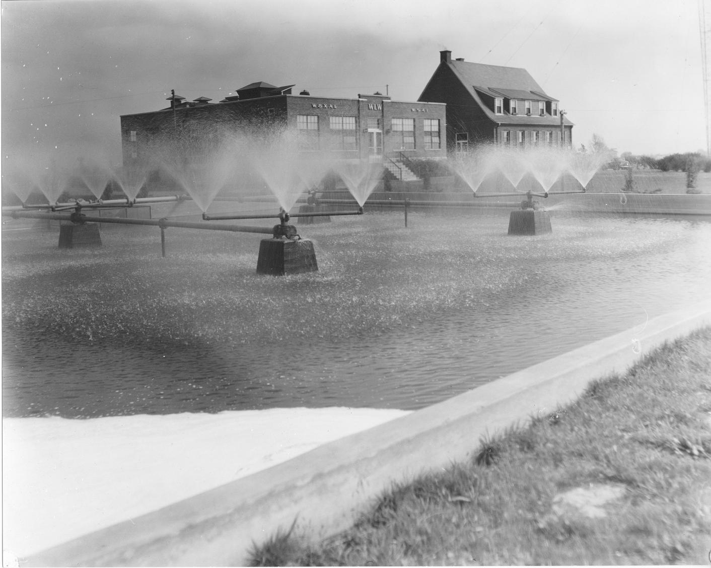
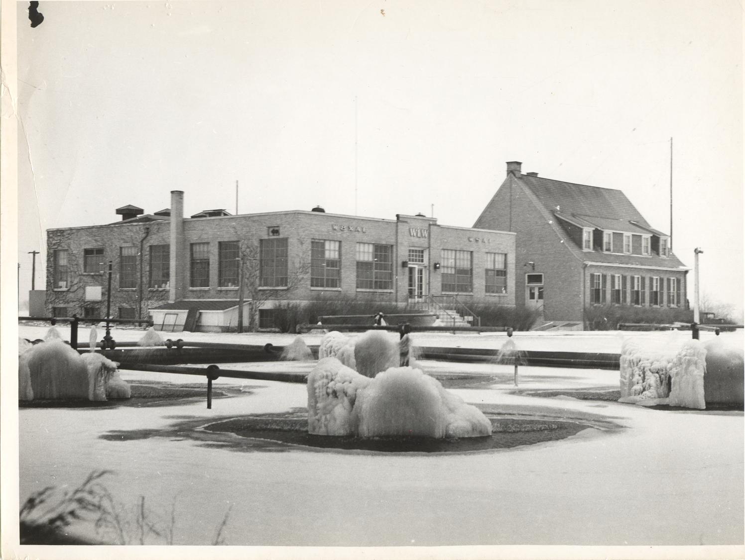
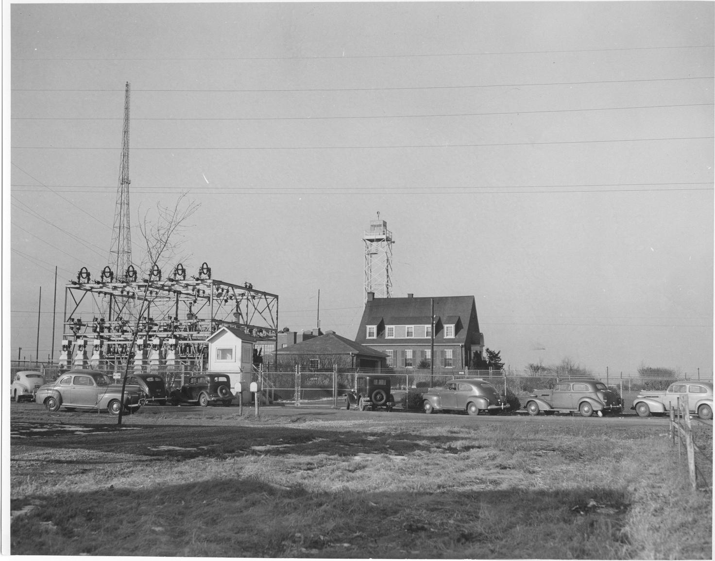
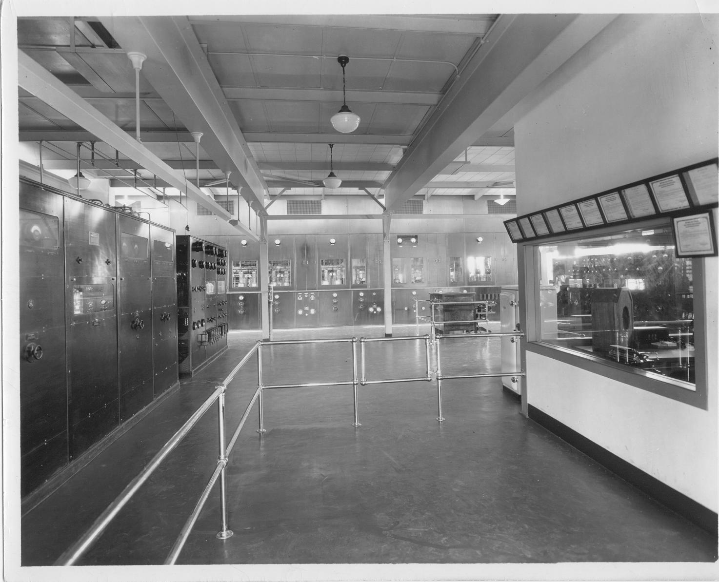
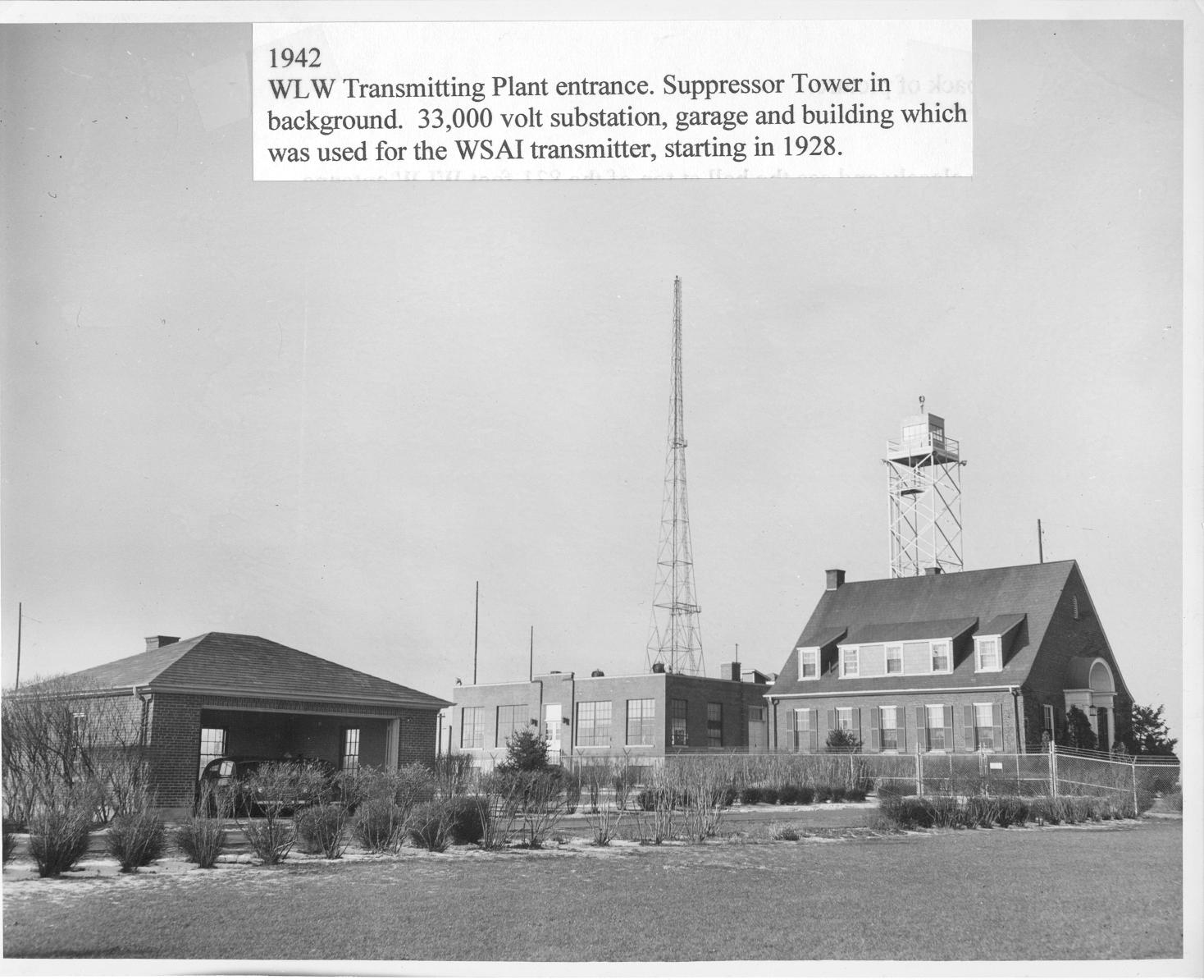
13. 1936 WLW transmitter site, Mason, Ohio. This is one of the best known photographs of the WLW transmitter site. Located about 25 miles north of Cincinnati, it serves a large portion of the U.S. with its 500,000 Watt voice. The spray pond circulates cooling water for the giant 100,000 Watt power tubes, of which there are twenty. The building in the foreground houses the giant half-million Watt transmitter. The house in the background originally contained the WSAI station transmitter. The inverted pyramid tower was built by Blaw-Knox in 1933 specifically for the 500,000 Watt operation. The base impedance of the tower is 390 Ohms and is fed with an antenna current of 35.7 Amperes of RF energy on 700 kc. 14. Spray Pond - water cooling system for the Type 862 tubes in the WLW 500,000 Watt transmitter. Note - the nozzles pointed upward for maximum cooling. 15. 1935 Spray Pond during winter at the WLW transmitter site. 16. 1942 WLW transmitter plant entrance. A suppressor tower is in the background. The building on the right housed the WSAI transmitter, starting in 1928. 17. 1934 A view of the WLW superpower half-million Watt transmitter of the Crosley Broadcasting Corp. This transmitter site is located at Mason, Ohio, approximately 25 miles north of Cincinnati. The original Western Electric 50,000 Watt transmitter is seen at the far left. It is used as an exciter of the 500,000 Watt amplifier, seen at the far end of the building. The control room is at the right. The main control desk can be seen a little to the right beyond the fence. All transmitters are controlled from this desk. The W8XAL transmitter can be seen at the far right through the control room windows. The transmitters and this building stand today, although somewhat modified, and is still the WLW transmitter site on 700 kc, 50,000 Watts. 18. 1942 Left to right, garage, WLW transmitter building, suppressor tower and Building used for WSAI transmitter, starting in 1928. |
|||||
19.jpg
169.74 KB |
20.jpg
190.42 KB |
21.jpg
183.40 KB |
22.jpg
147.88 KB |
23.JPG
106.86 KB |
24.jpg
163.96 KB |
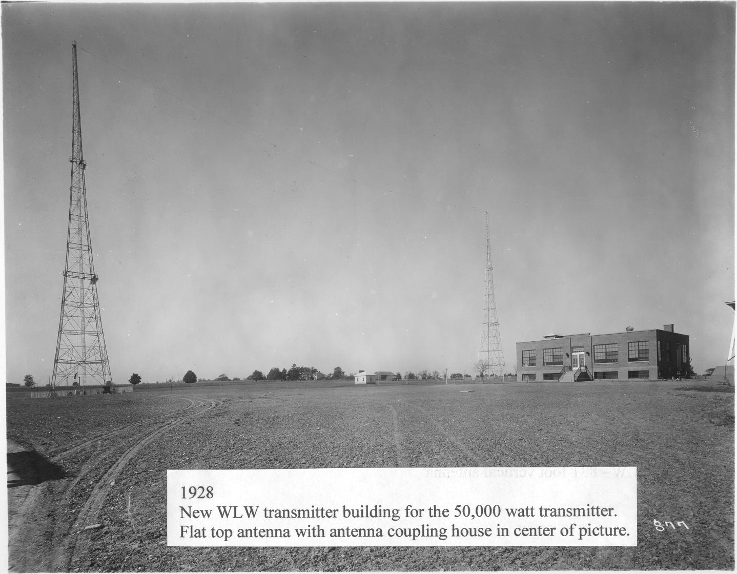
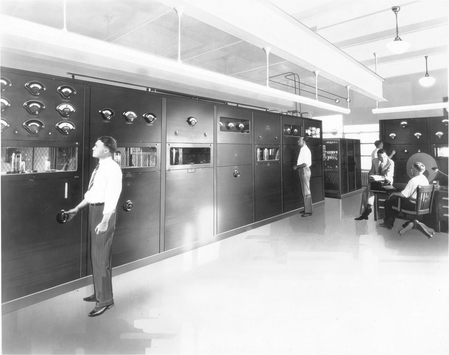
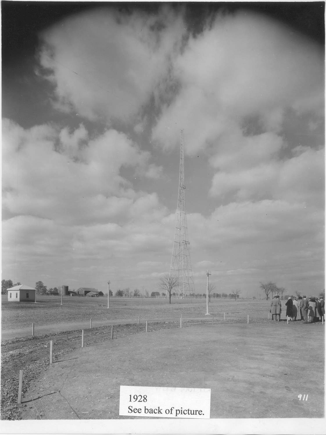
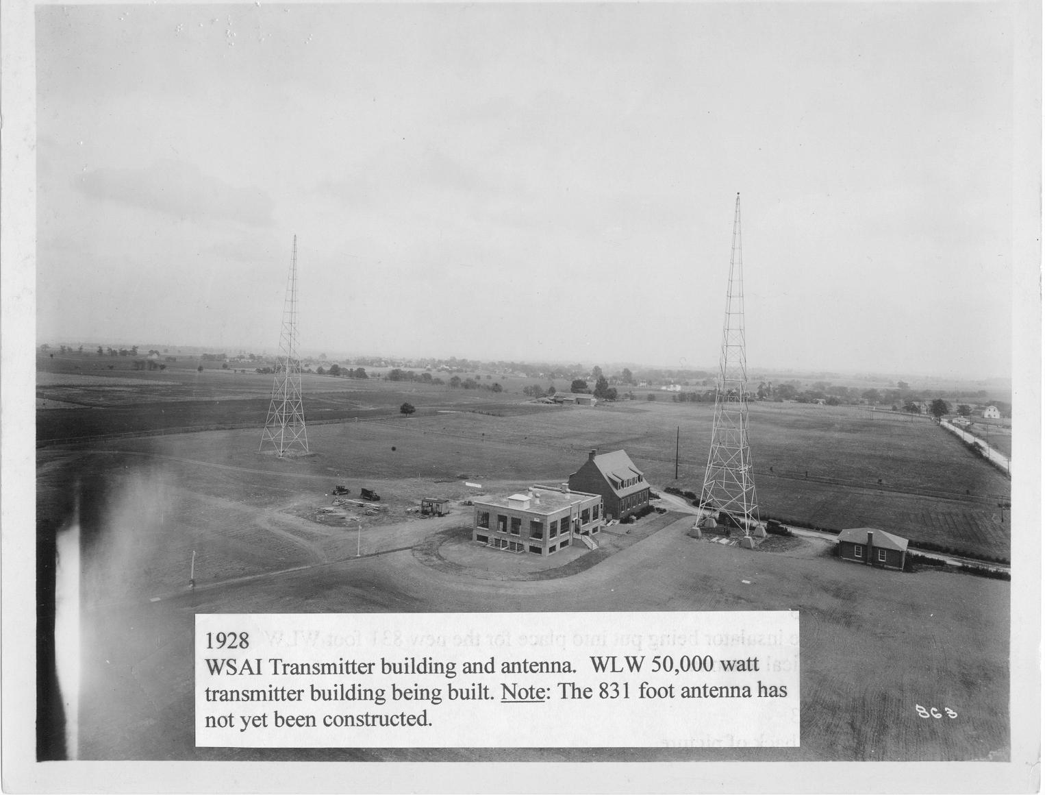
19. 1928 New WLW transmitter building on the left. WSAI transmitter building on the right with one of the towers for the WSAI flat top antenna. 20. 1928 New WLW transmitter building. 21. 1928 New WLW transmitter building for the 50,000 Watt transmitter. Flat top antenna with antenna coupling house in center of picture. 22. 1928 A view of the Western Electric 7A transmitter installed at the WLW Mason, Ohio plant. The original transmitter became the exciter/driver for the 500,000 Watt amplifier later on. When the station ran at 500,000 Watts, the final RF amplifier had its own separate high level modulator. The modulator section of this W.E. 7A transmitter was disabled and the RF output was divided and fed the grids of the half-million Watt final amplifier. At the same time the antenna was disconnected from the W.E. 7A and re-connected to the half-million Watt amplifier. 23. 1928 A view of the WLW transmitter site at Mason, Ohio. This is looking to the west from the transmitter building toward the newly built antenna coupling house for the “T” antenna. One of two 300 foot towers is shown that support the horizontal antenna. The downlead from the center can just bee seen connected to the coupling house. The transmitter is a Western Electric 50,000 Watt 7A feeding this antenna via a two-wire open wire transmission line, 24. 1928 WSAI transmitter building and antenna. WLW 50,000 Watt transmitter building under construction. Note: the 831 foot antenna has not yet been built. |
|||||
25.jpg
182.60 KB |
26.jpg
190.11 KB |
27.jpg
143.91 KB |
28.jpg
127.59 KB |
29.jpg
203.93 KB |
30.JPG
168.78 KB |
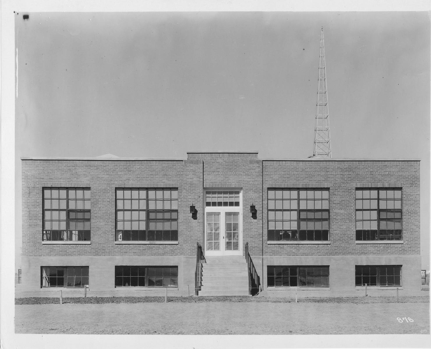
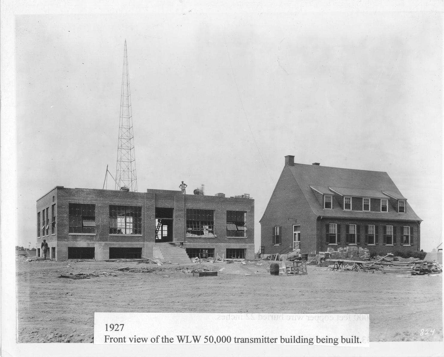
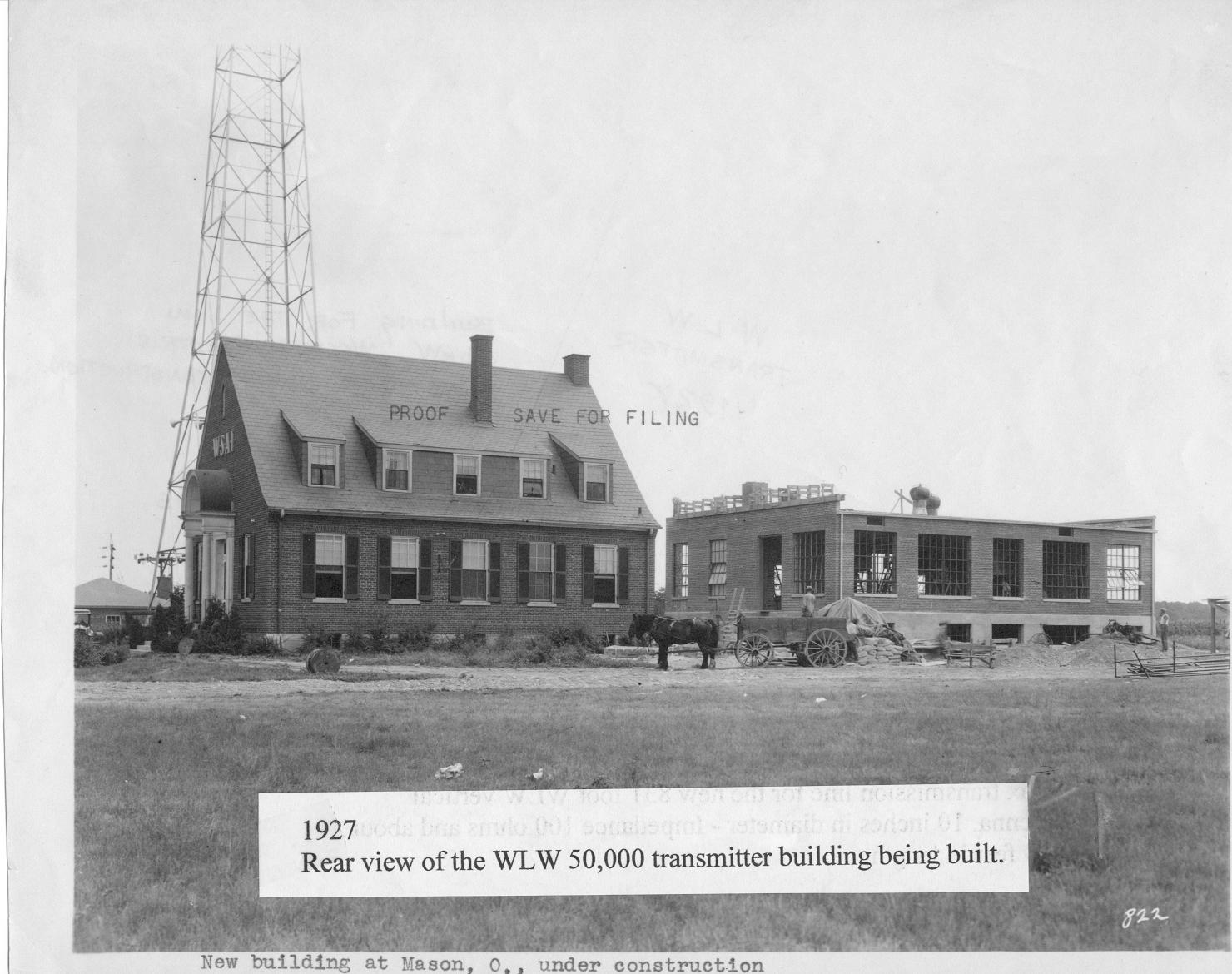
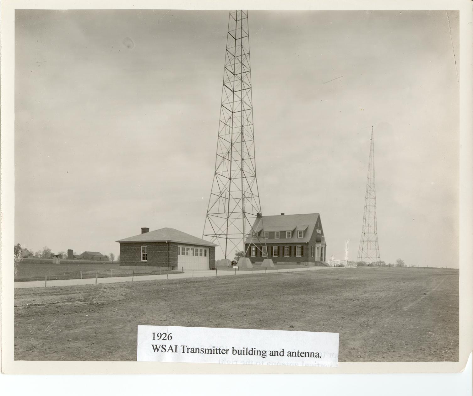
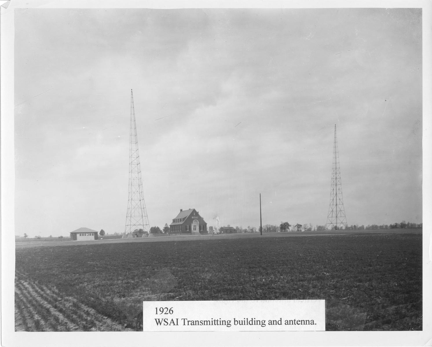
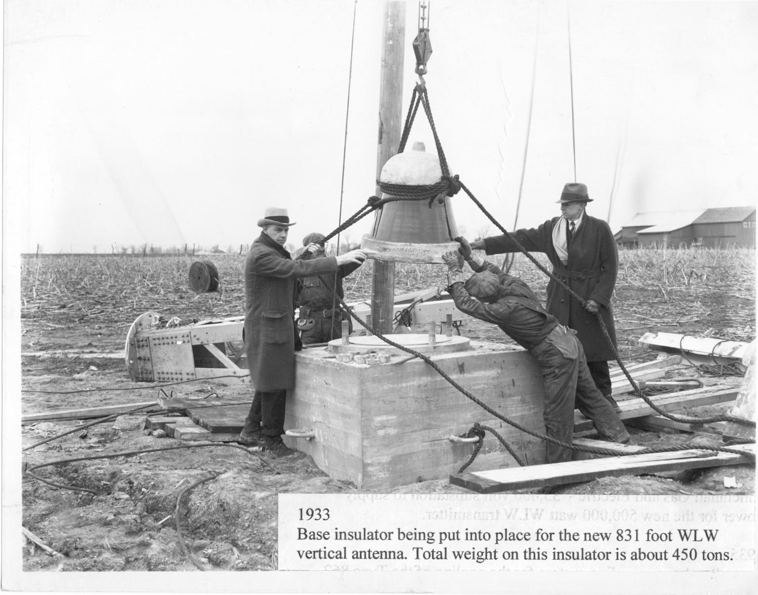
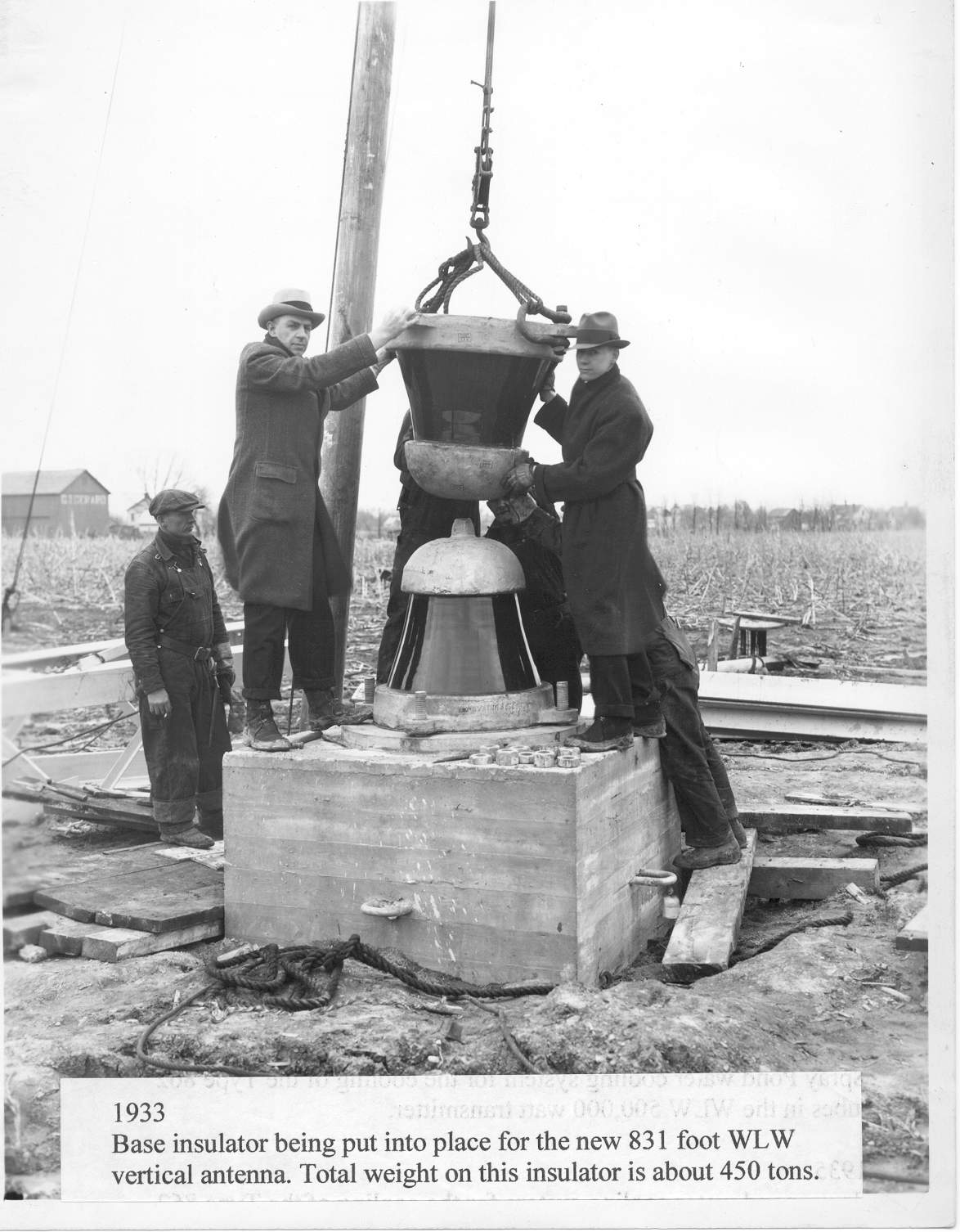
25. 1927 Front view of the WLW 50,000 Watt transmitter building under construction. 26. 1927 Rear view of the WLW transmitter build under construction. Note the horse drawn wagon bringing construction supplies. 27. 1926 WSAI transmitter building and antenna. 28. 1926 WSAI transmitter building and antenna 29. 1933 Base insulator being put into place for the new 831 foot WLW vertical antenna. Total weight on this insulator is about 450 tons. 30. 1933 Base insulator being put into place for the new 831 foot WLW vertical antenna. Total weight on this insulator is about 450 tons. |
|||||
31.JPG
165.71 KB |
32.jpg
275.86 KB |
33.jpg
253.03 KB |
34.jpg
280.39 KB |
35.JPG
266.44 KB |
36.jpg
152.52 KB |
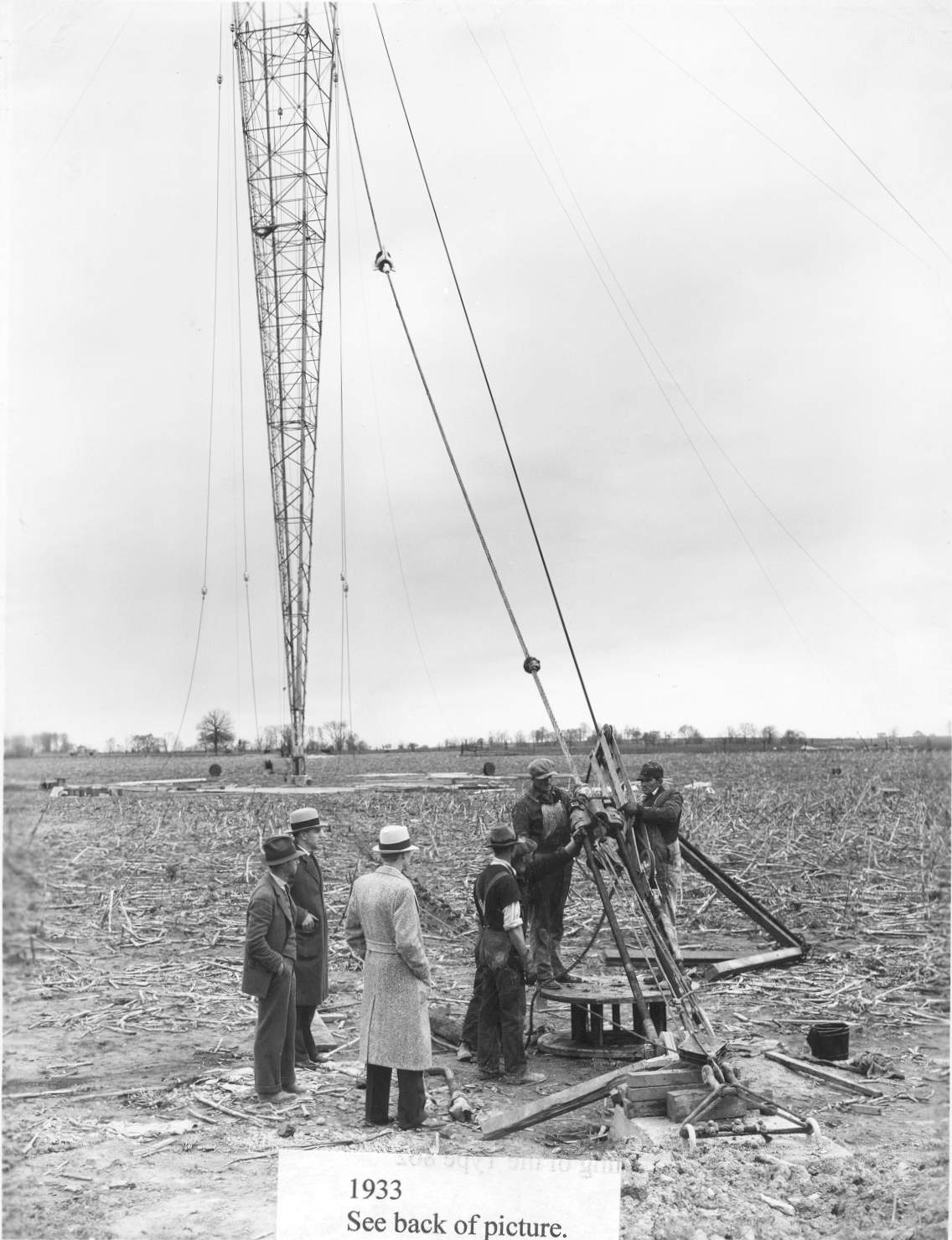
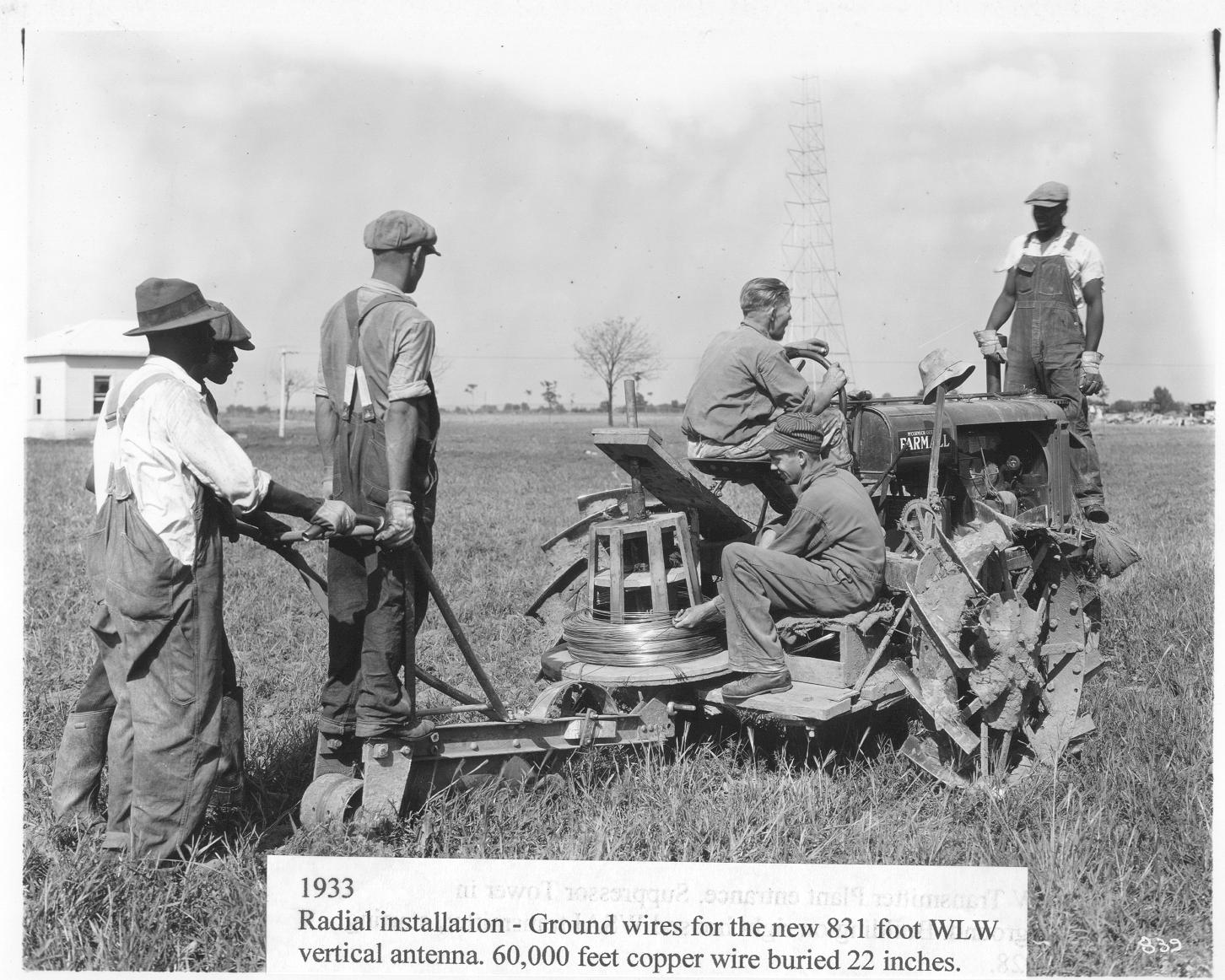
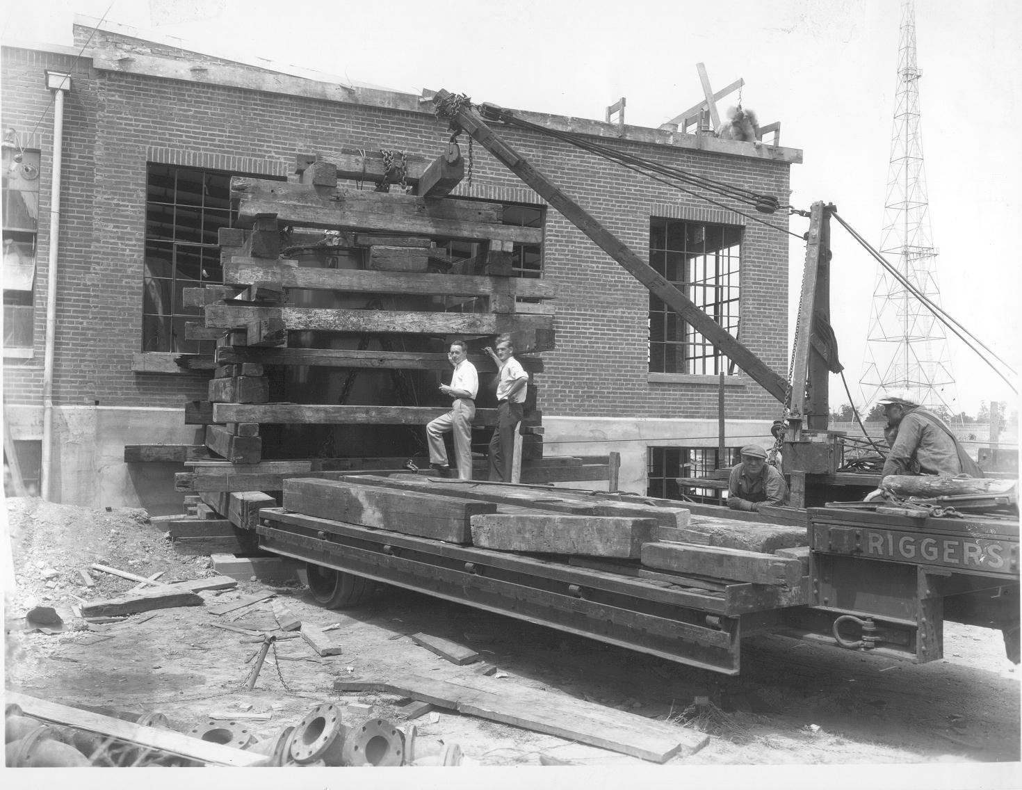
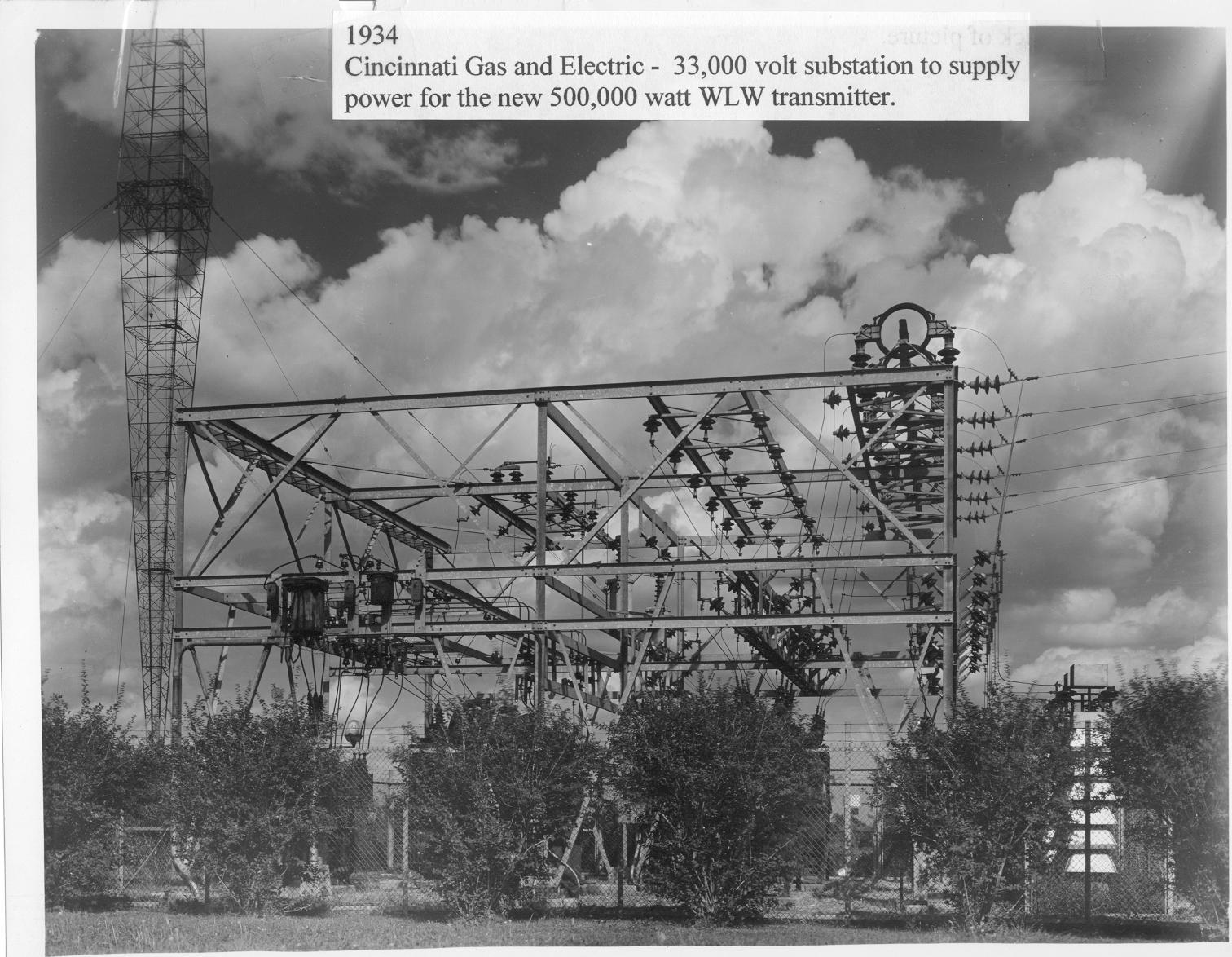
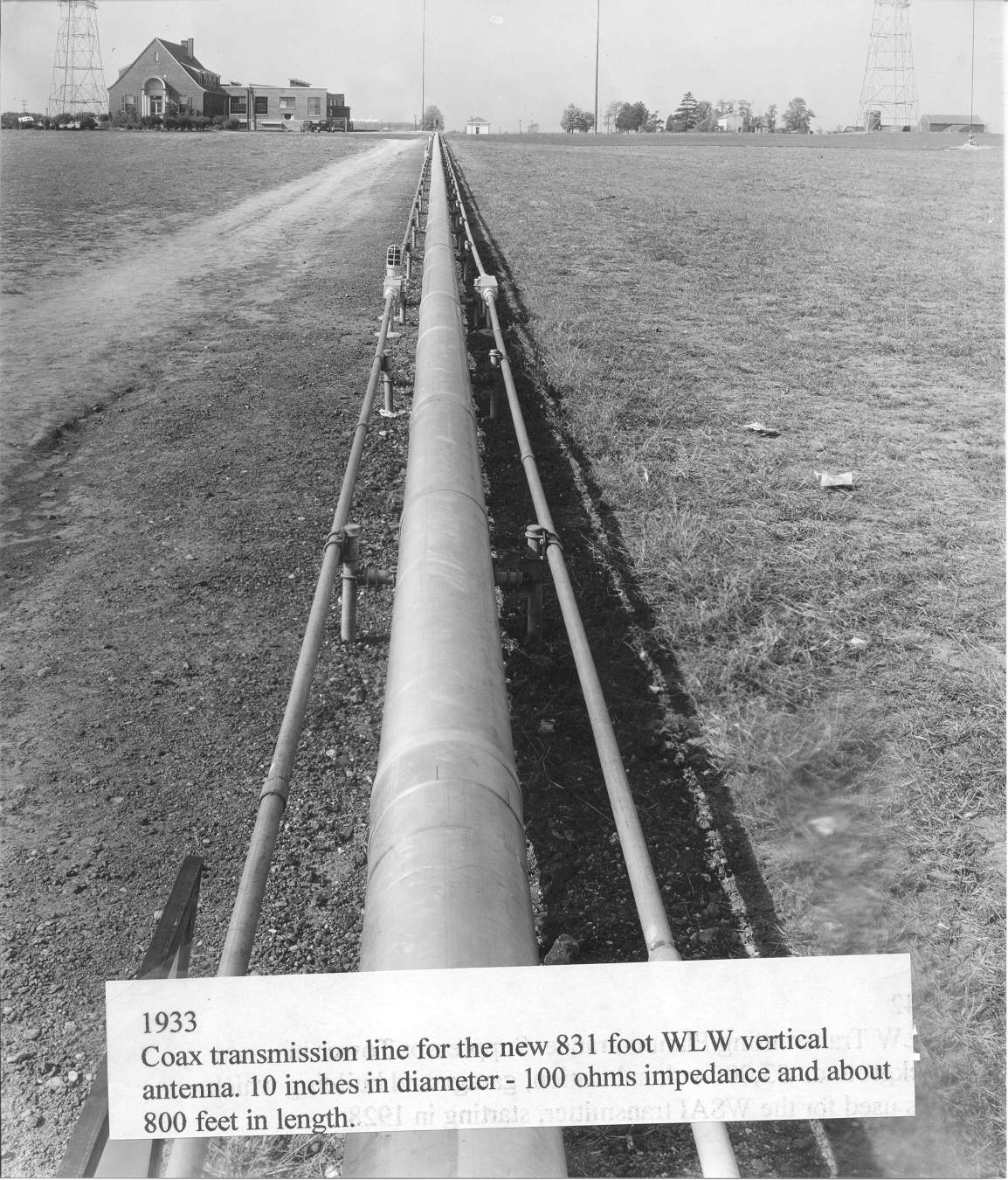
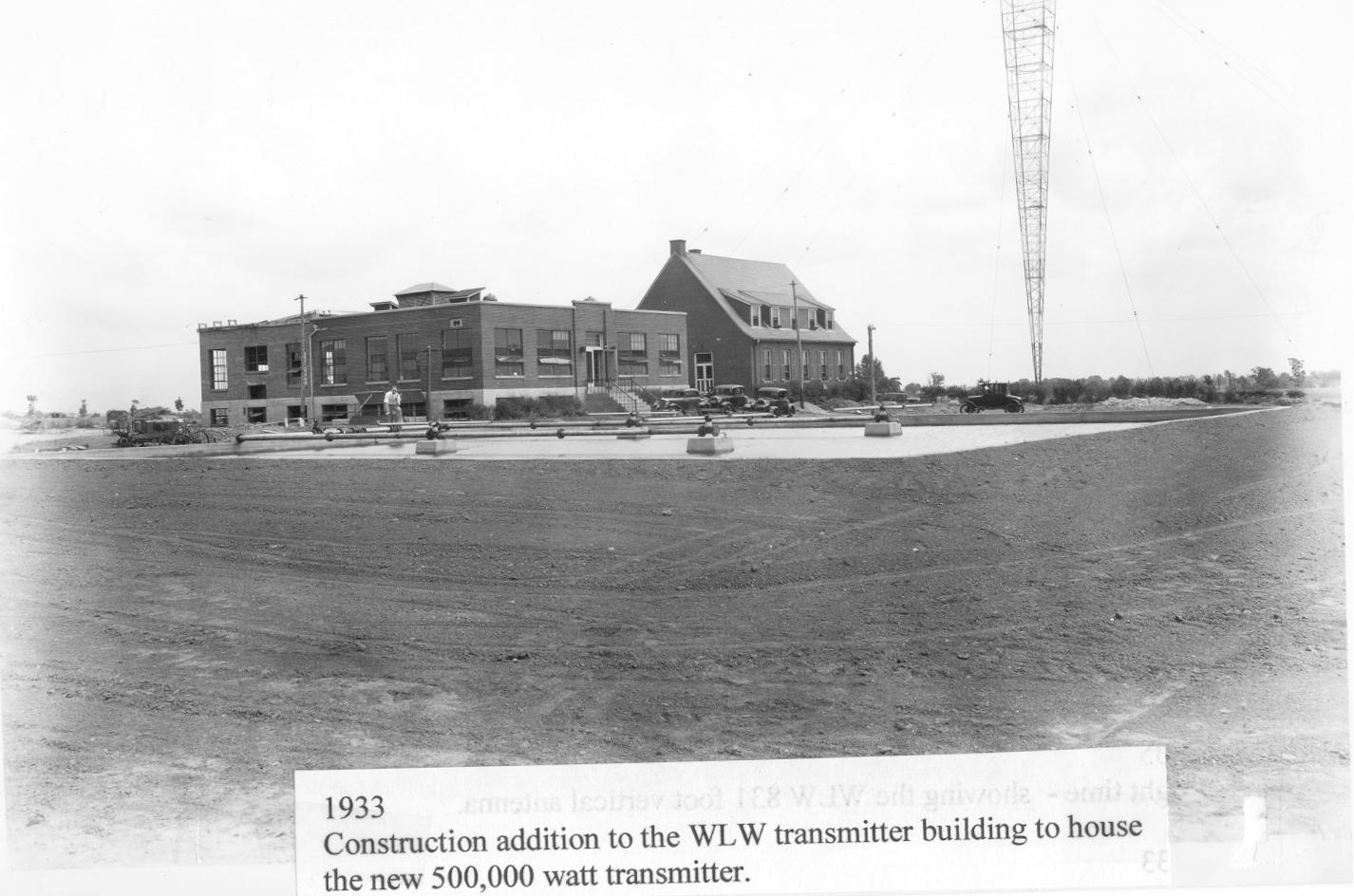
31. 1933 (February) Unidentified crew and WLW personnel observing ower guy cable tensioning during erection of the 831 foot Blaw-Knox pyramid tower. This tower is designed for 500,000 Watt radiation and is 5/8 of a wave at 700 kc. 32. 1933 Radial installation. Ground wires for the new 831 foot WLW vertical antenna. 60,000 feet of copper wire buried 22 inches. 33. 1934 Engineers in charge of construction of the new 500,000 Watt transmitter for WLW were confronted with many perplexing problems. One of them was the installation of the huge 100,000 pound audio modulation transformers. It became necessary to dig a large excavation outside the transmitter building in order to lower this one of two giant transformers into place in the basement of the building. These giant transformers were built by Westinghouse Electric and are rated at 180 kVA with a frequency response from 30 to 10,000 cycles per second. They are oil insulated and self cooled. 34. 1934 Cincinnati Gas & Electric 33,000 Volt substation to supply power for the WLW - W8XAL transmitter. This is arranged with switching equipment for two 33 kV power lines which come to the transmitter from different directions. In case of trouble or interruption of service on one circuit this equipment switches over to the other circuit. This guarantees a minimum of interruptions to the electric power required for the transmitters. 35. 1933 Coaxial transmission line for the new 831 foot WLW vertical antenna. It is 10 inches outside diameter, 100 Ohms impedance and about 800 feet in length. 36. 1933 Construction addition to the WLW transmitter building to house the new 500,000 Watt transmitter. |
|||||
37.JPG
95.97 KB |
38.JPG
66.21 KB |
39.JPG
119.86 KB |
40.JPG
118.68 KB |
41.jpg
245.91 KB |
42.jpg
285.10 KB |
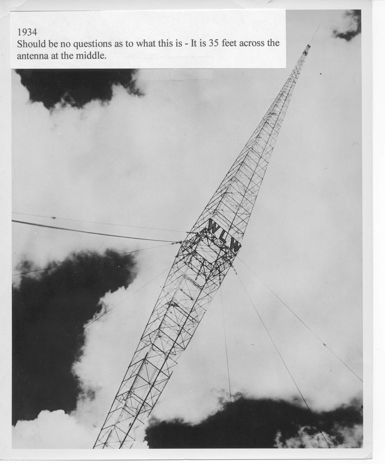
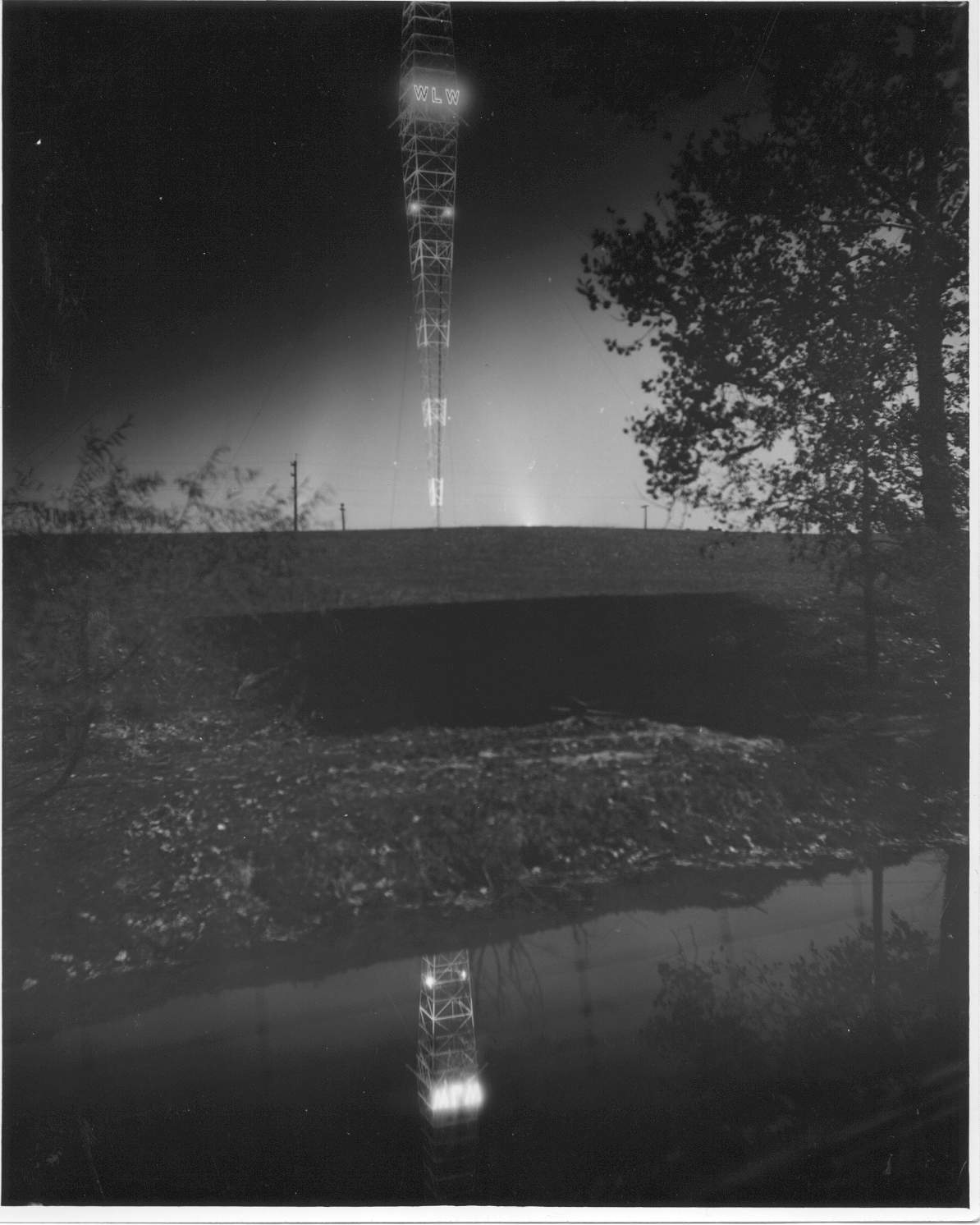
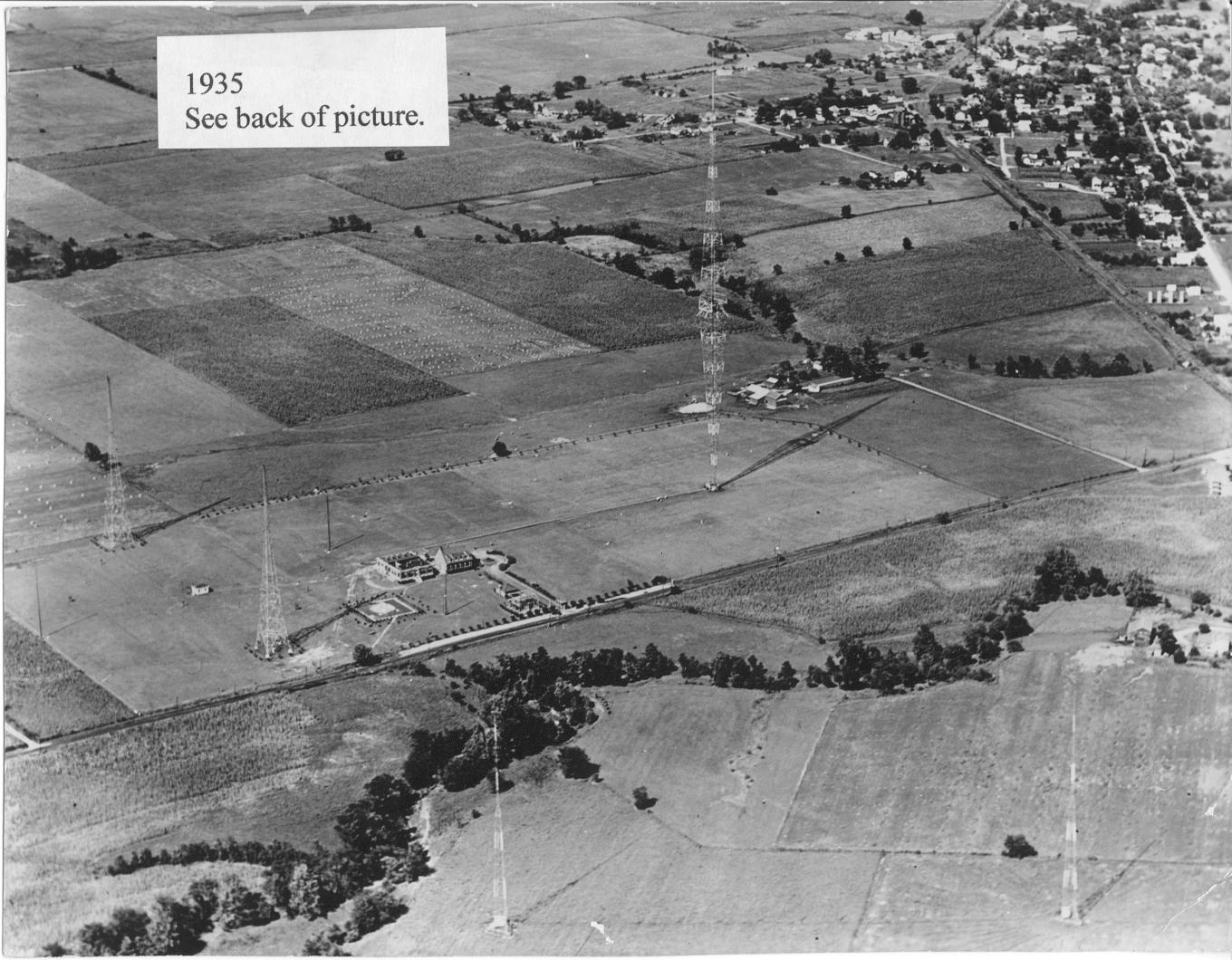
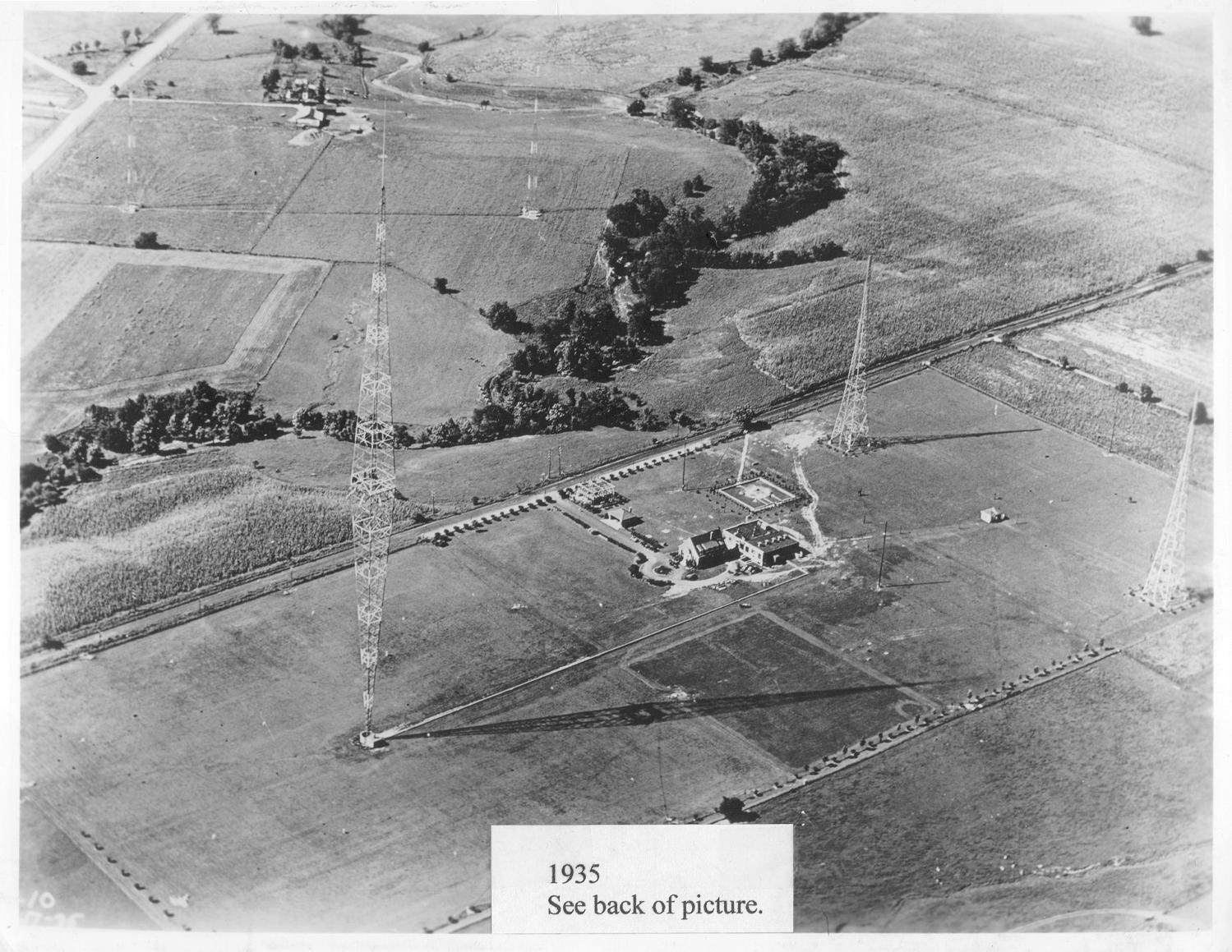
37. 1934 Look closely and you can see the ball at the top of the WLW 831 foot antenna. 38. 1934 Look closely and you can see the ball at the top of the WLW 831 foot antenna. 39. 1934 The WLW tower is 35 feet across at the middle. 40. 1935 The WLW 831 foot vertical antenna tower at night. 41. 1935 Overall view of the WLW transmitter site looking northeast. Suppressor towers in foreground, 1928 flat top antenna on the left and 831 foot vertical radiator on the right. The vertical antenna suppressor towers are on the south side to Tylersville road. The horizontal antenna was used prior to the vertical antenna east of the transmitter buildings. 42. 1935 Overall view of the WLW transmitter site looking southwest. Everybody’s Farm is in the upper left of the picture. This view encompasses the WLW main Blaw-Knox vertical tower, the horizontal “T” antenna on the far right over the coupling house, and the suppressor towers on the south side of Tylersville Road. |
|||||
43.JPG
228.65 KB |
44.jpg
175.54 KB |
45.JPG
165.80 KB |
46.jpg
237.26 KB |
47.jpg
230.06 KB |
48.jpg
204.22 KB |
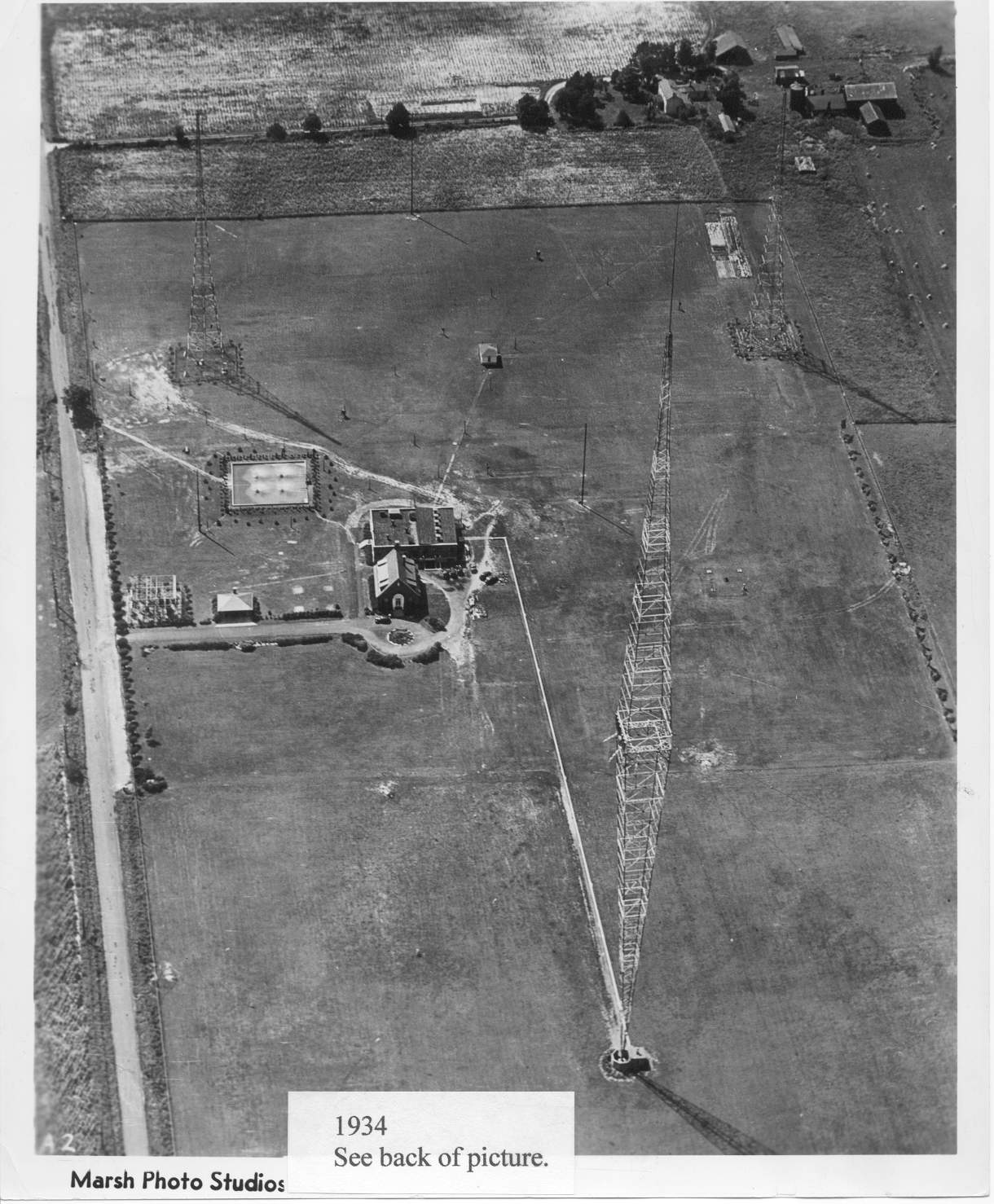
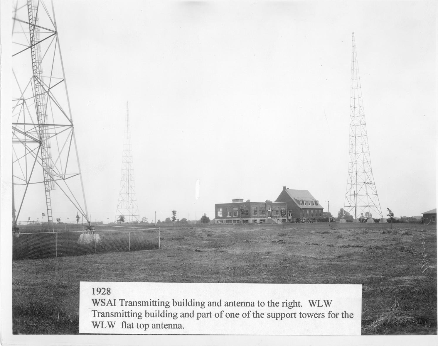
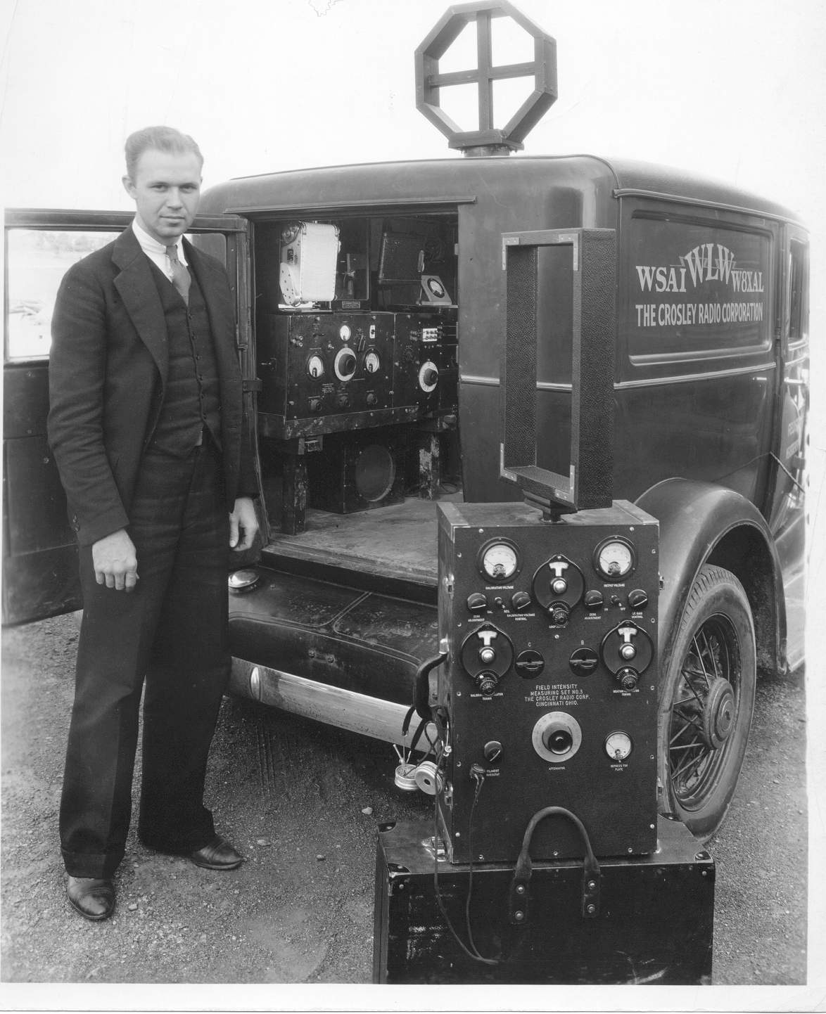
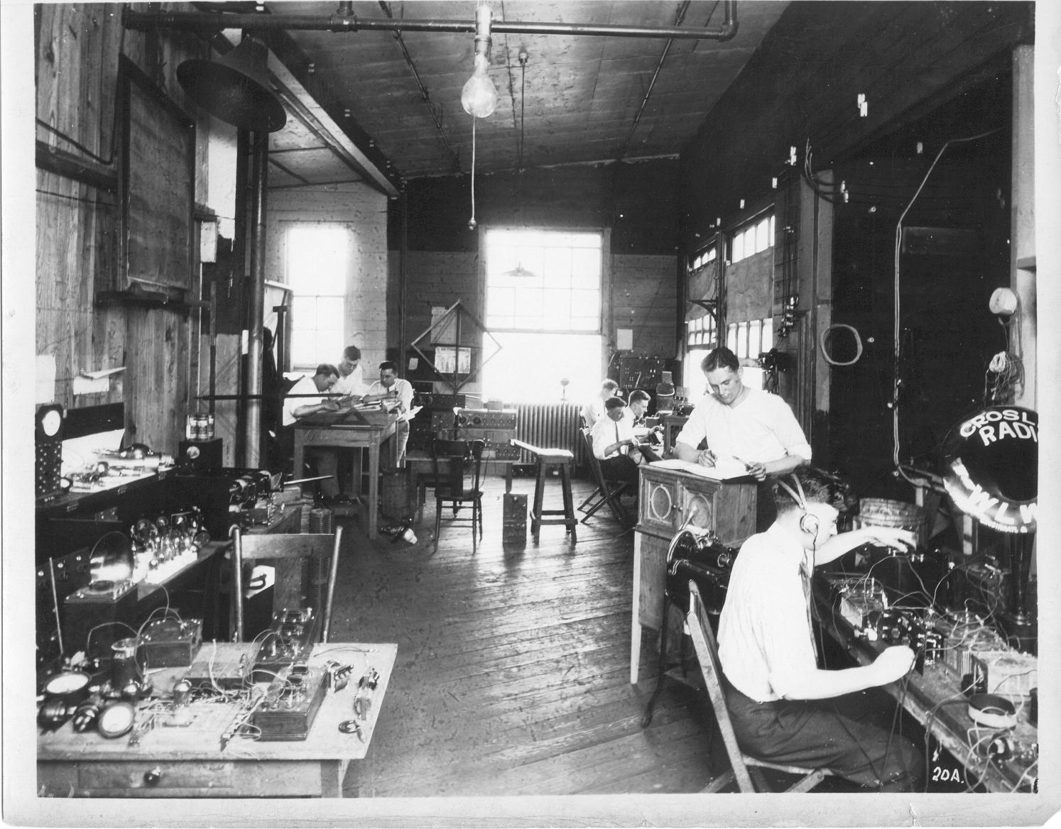
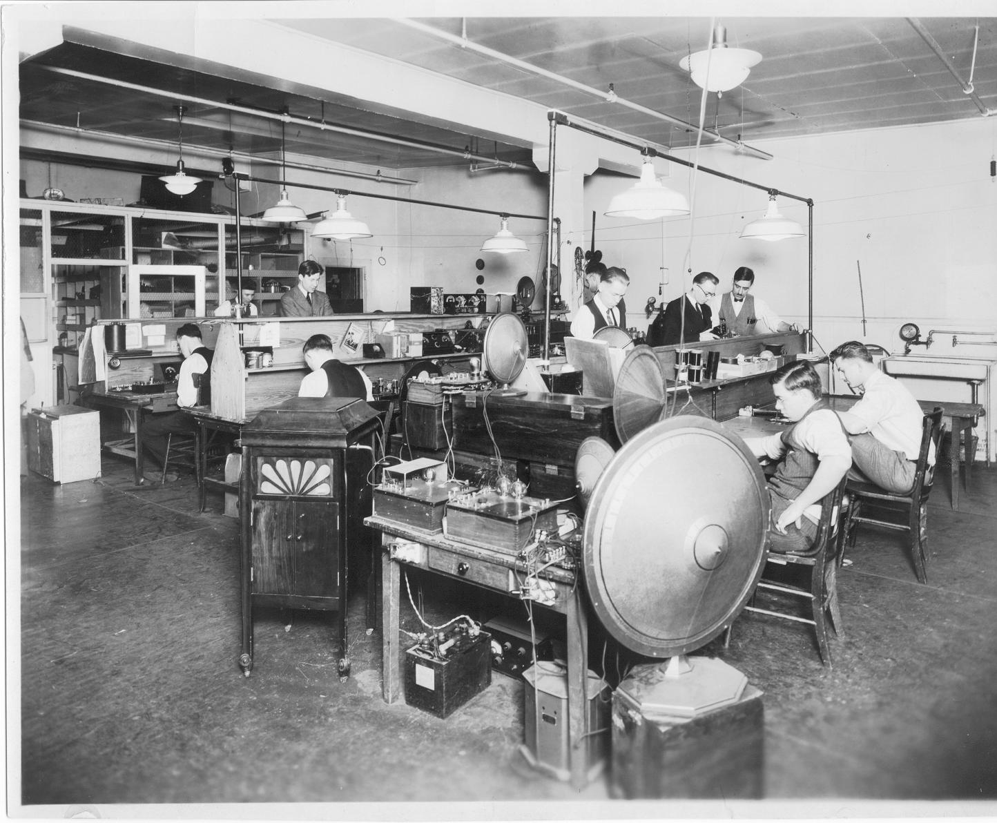
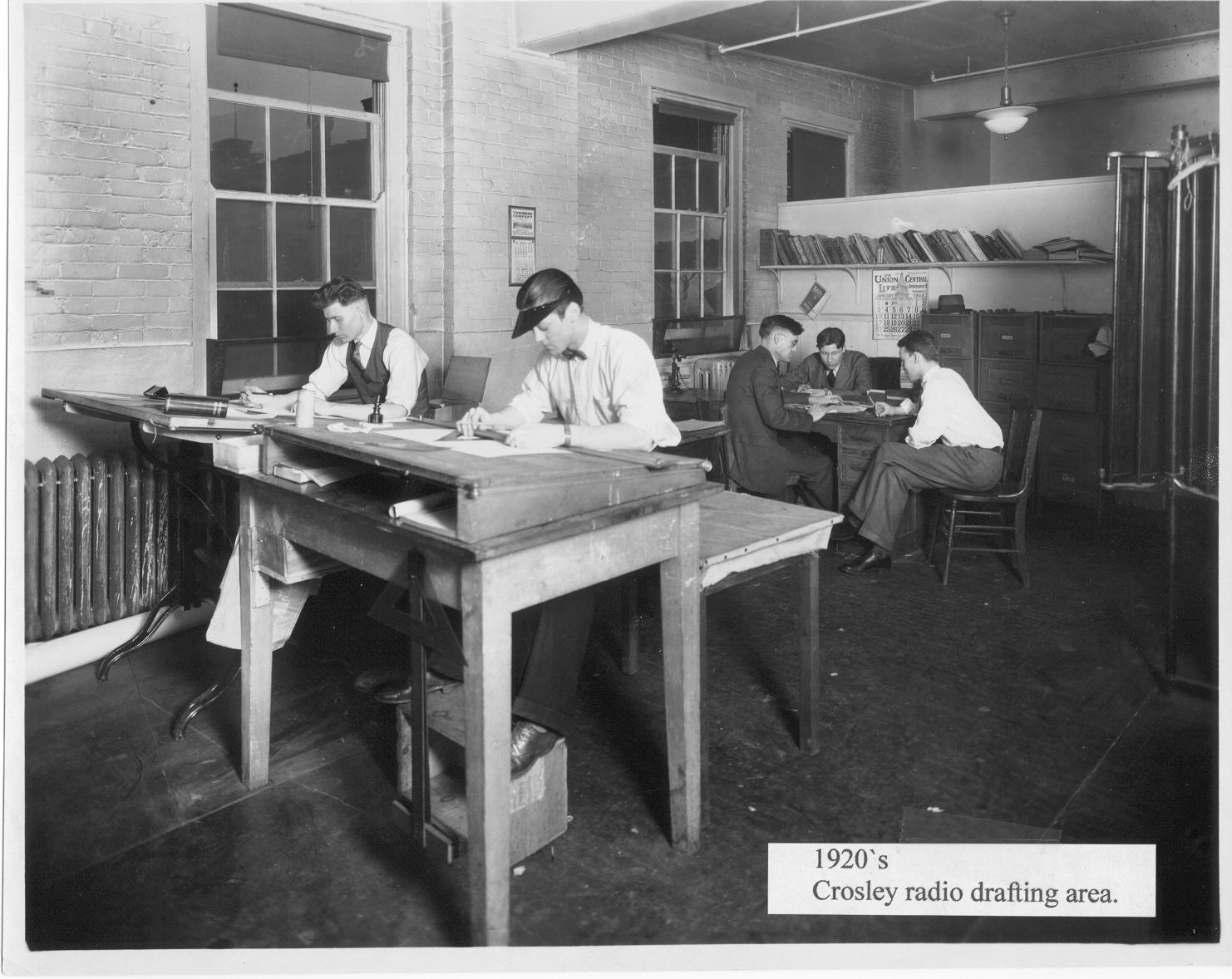
43. 1934 Aerial view of the WLW transmitter site at Mason, Ohio. The 831 foot Blaw-Knox pyramid tower is the foreground. The tower is 5/8 wavelength at too kc. The WSAI house and main transmitter buildings are shown. The water cooling spray pond is at the upper left. At the top is the antenna coupling house between the two 300 foot towers that support the “T” wire cage horizontal antenna (now used as an auxiliary). Tylersville Road is seen at the far left. Notice the the pier foundations of the two 300 foot towers that used to sit over the WSAI house. These were moved to their present location west of the transmitter building. 44. 1928 WSAI transmitter building and antenna to the right. WLW transmitter building and part of one of the support towers for the WLW flat top antenna. 45. 1935 This field strength measuring equipment was used to plot measurements of radiated signal strength. This was especially true in the case where the Federal Radio Commission of the U.S. Commerce Dept. (the forerunner of the F.C.C.) Ordered the management of WLW to reduce signal strength in the vicinity of Toronto, Ontario, Canada after the Canadian government protested the interference being experienced by the superpower adjacent channel station WLW. This equipment was used to plot graphic records of signal strength before and after a suppressor antenna was conceived, engineered and built by the WLW engineering staff. A brilliant job of radio engineering, as a pamphlet for Esterline-Angus graphic recorders described it. Inside the truck can be seen a graphic chart recorder mounted atop the General Radio Standard Signal Generator. 46. 1920s Crosley Radio Labs., Cincinnati, Ohio. 47. 1920s Crosley Radio Labs., Cincinnati, Ohio. 48. 1920s Crosley Radio drafting area. Cincinnati, Ohio. |
|||||
49.jpg
257.93 KB |
50.JPG
145.30 KB |
51.JPG
96.08 KB |
52.jpg
196.45 KB |
53.JPG
92.64 KB |
54.jpg
358.17 KB |
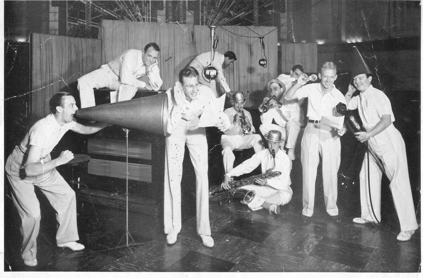
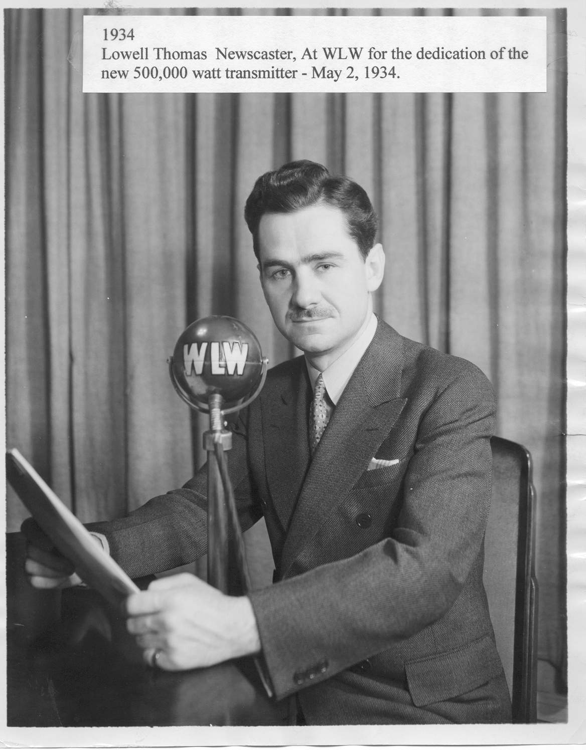
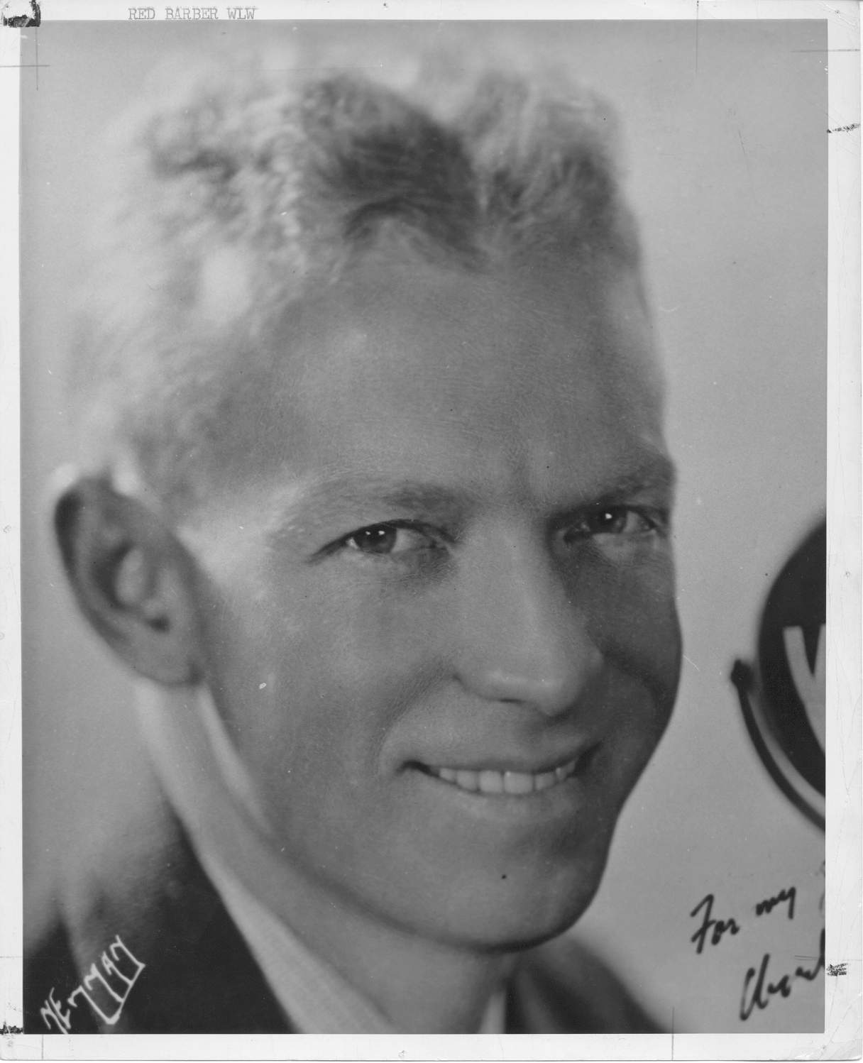
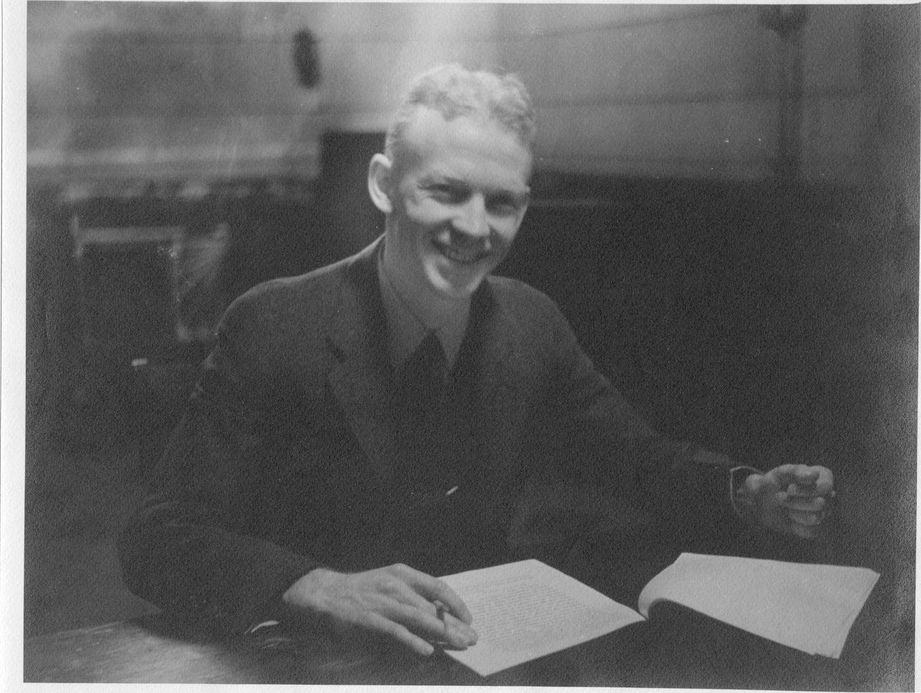
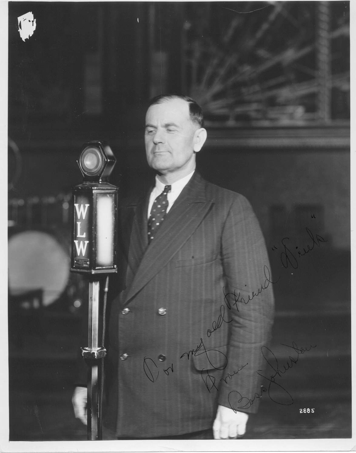
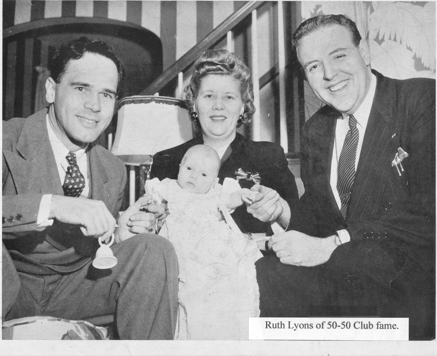
49. THE TOY BAND IN ACTION. Jack Edmonds adopts true Movie style (left) in directing the dramatics, while Uncle Durwood Kirby, announcer, gets instructions on how to be a lion. At the right, Cousin Charlie Dameron, wearing the dunce hat, listens to Uncle Red Barber’s sports talk while Uncle Red holds a light bulb to see his script. On the floor sits Uncle Joe Lugar with his big bass saxophone. The trumpeters are Uncle Doc Wildeson, left, and Uncle Holly Todd. Behind him are Uncle Byron Winget, the sound man, is creating the bleat of a lamb, while Uncle Tommy Richey gets on top of his xylophone (rear) to produce the effect of an elephant playing Yankee Doodle on a harmonica or something. Uncle Jack Saatkamp, who plays the “silent stooge” in this particular “drama” is perched on his celeste. 50. 1934 Lowell Thomas, newscaster, at WLW for the dedication of the new 500,000 Watt transmitter, May 2, 1934. 51. 1936 Red Barber, Cincinnati Reds baseball announcer. 52. 1936 Red Barber, Cincinnati Reds baseball announcer. 53. Boss Johnson - WLW humorist from middle 1930s to 1950s. 54. Ruth Lyons of 50-50 Club fame. |
|||||
55.jpg
505.28 KB |
56.jpg
159.12 KB |
57.JPG
73.54 KB |
58.jpg
173.84 KB |
59.jpg
64.95 KB |
60.JPG
206.35 KB |
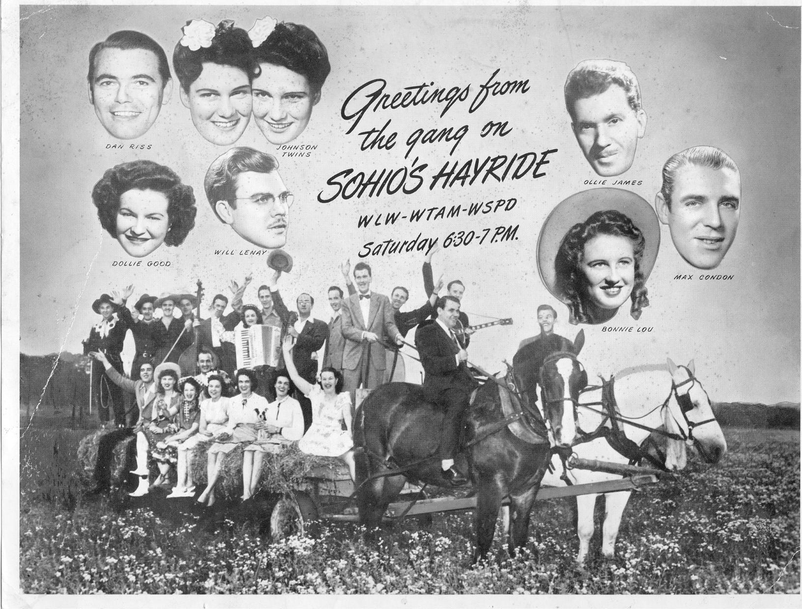
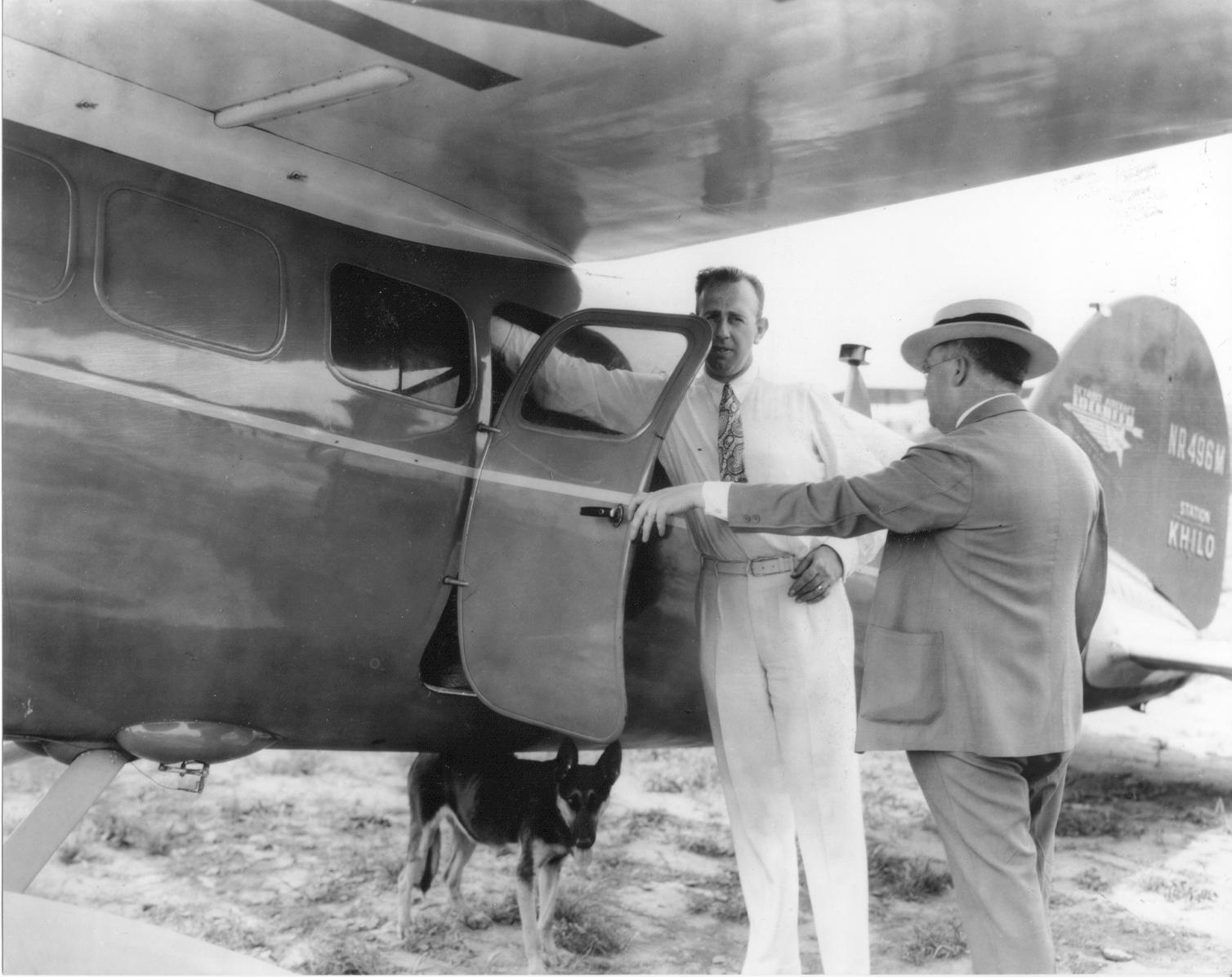
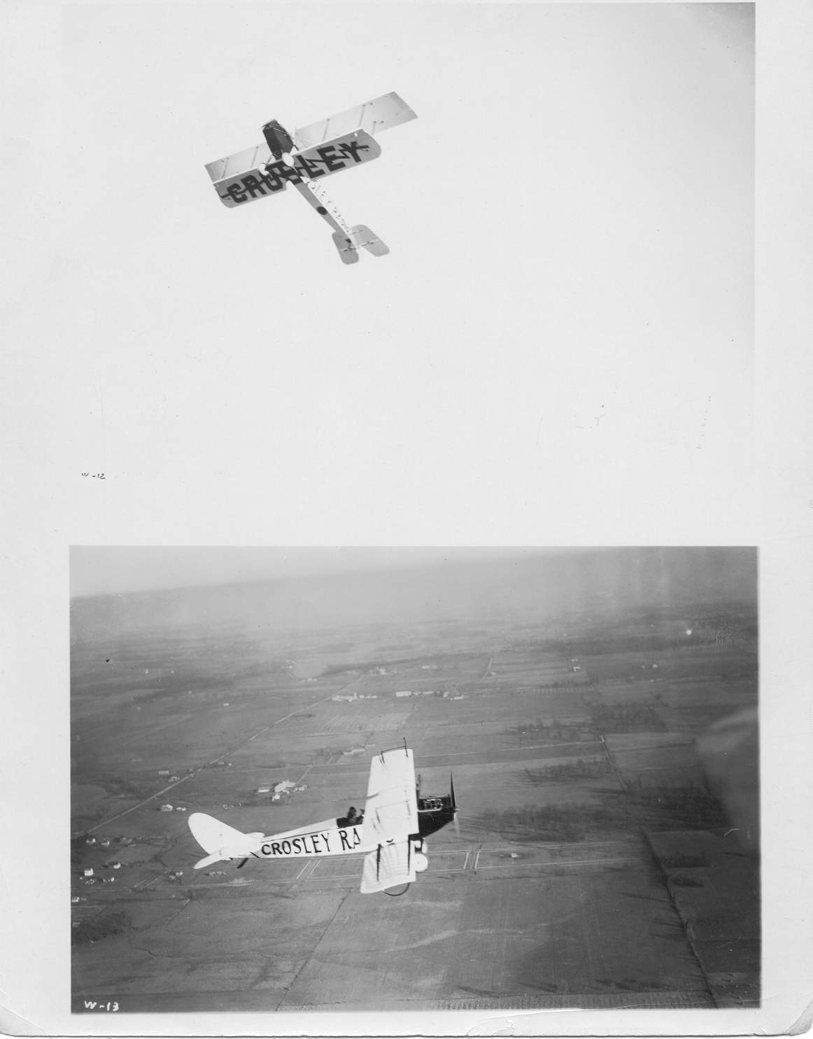
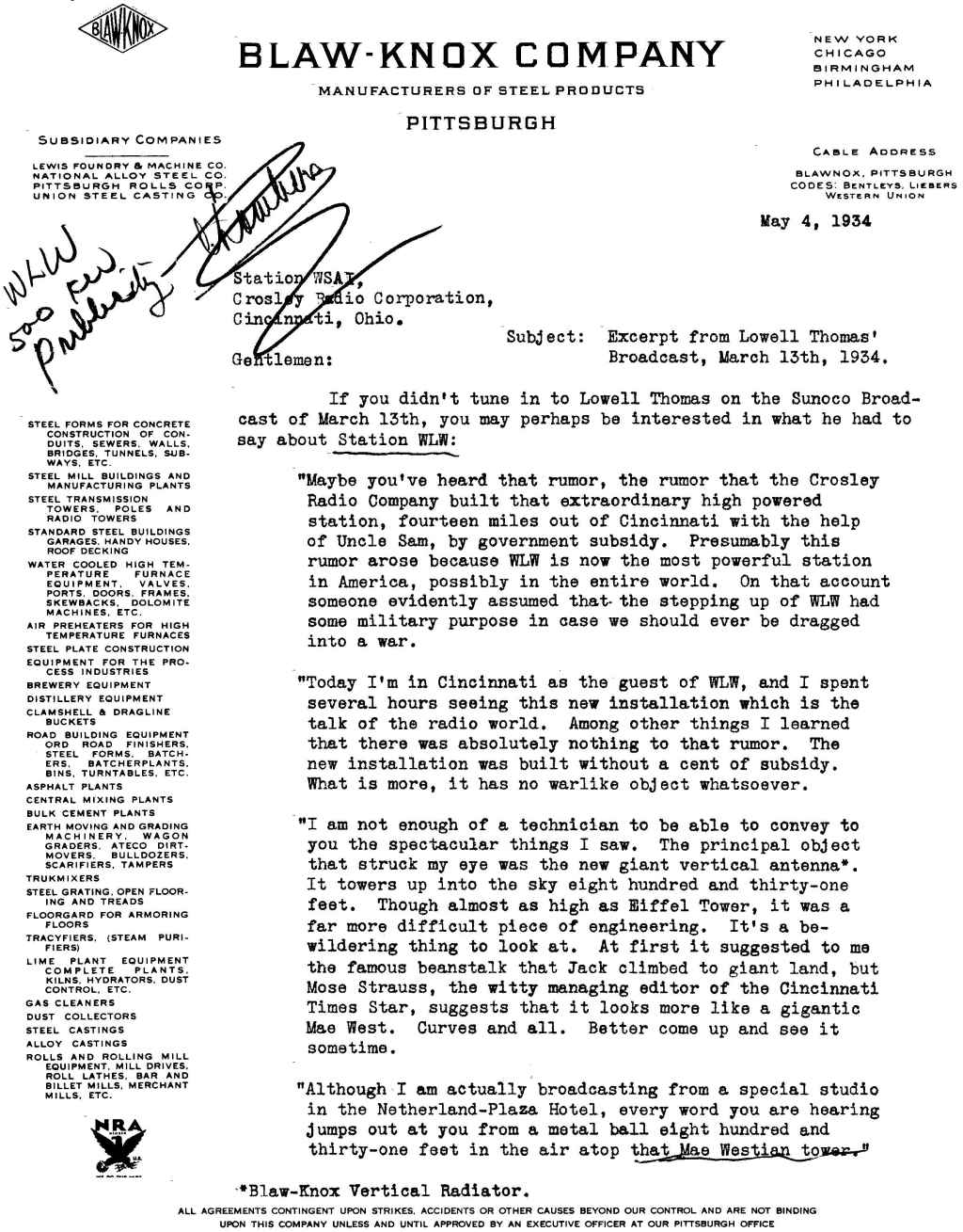
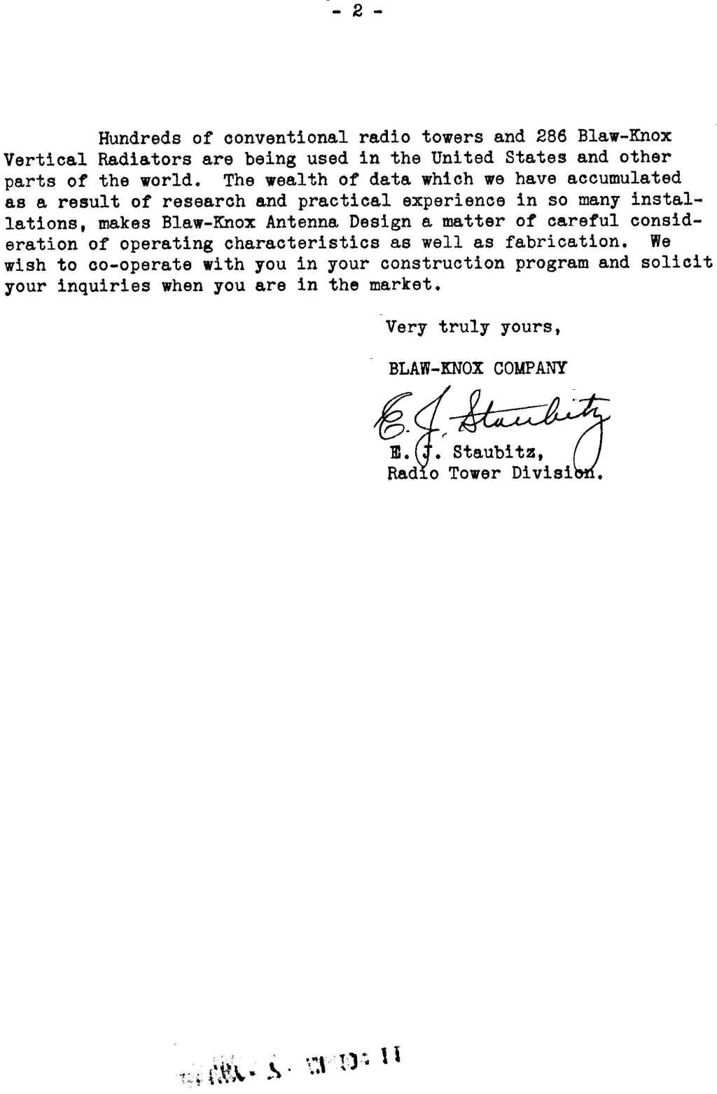
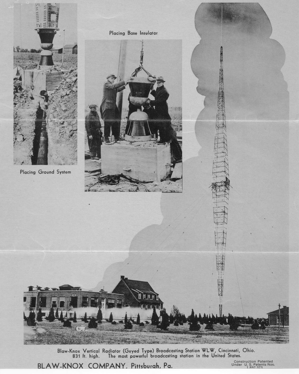
55. Sohio’s Hayride. 56. Powell Crosley Jr. and the flyer -1930s. 57. Crosley advertising plane of the 1920s. 58. Blaw-Knox page 1. 59. Blaw-Knox page 2. 60. Blaw-Knox page 3. |
|||||
61.jpg
94.27 KB |
62.jpg
140.21 KB |
63.jpg
94.96 KB |
|||
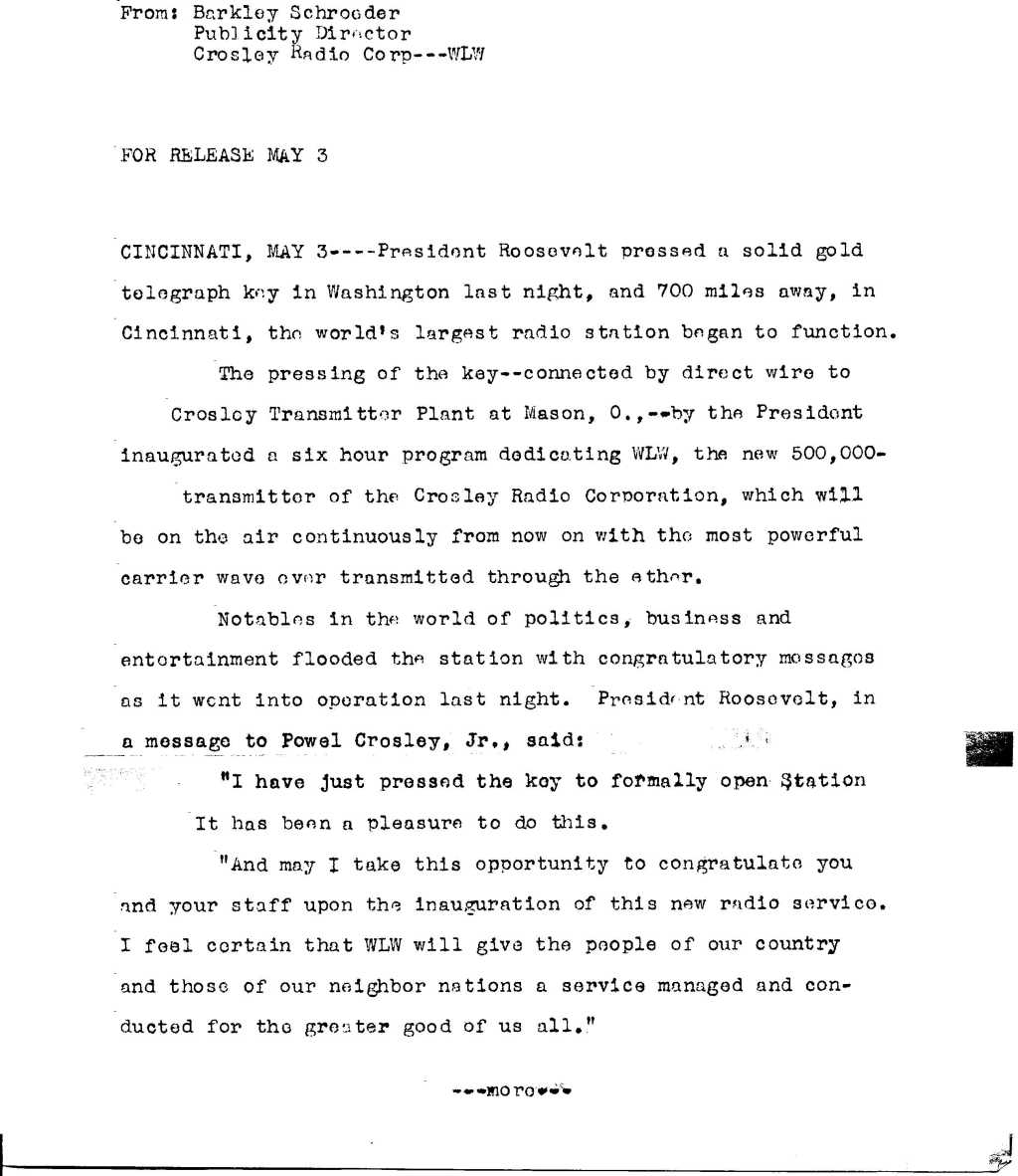
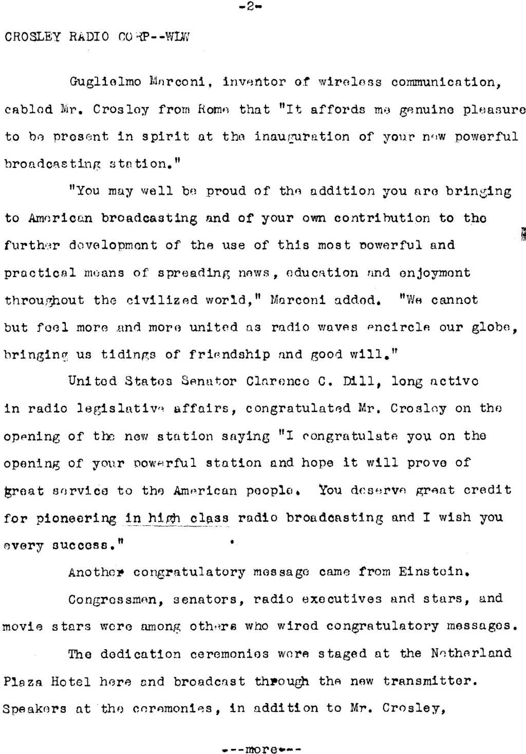
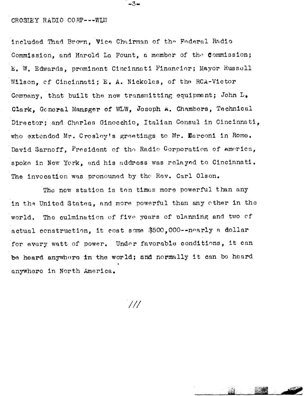
61. Crosley PR page 1 62. Crosley PR page 2 63. Crosley PR page 3 |
|||||