Front View
|
Clicking
HERE or on the image at left
brings up a larger version of the
photo .
|
|
Shown above is my latest build completed and tested on Christmas Eve, 2018. It's an HF 160-10 meter HF linear amplifier powered by two Eimac 4CX250B power tetrodes. So far I've made several contacts with signal reports indicating about 15db increase in signal strength on the receive end with the amplifier in line. My goal was to build a relatively small desktop amplifier in the 500 watt class which would operate off of household 120VAC power. It also needed to be driven by most conventional 100 watt class transceivers (I use a Kenwood TS590). So a 100 watt set of non-inductive swamping resistors are installed ahead of the control grids to provide the proper loading required for most modern transceivers. A side benefit is no neutralization is required for operation across the entire HF band. |
|
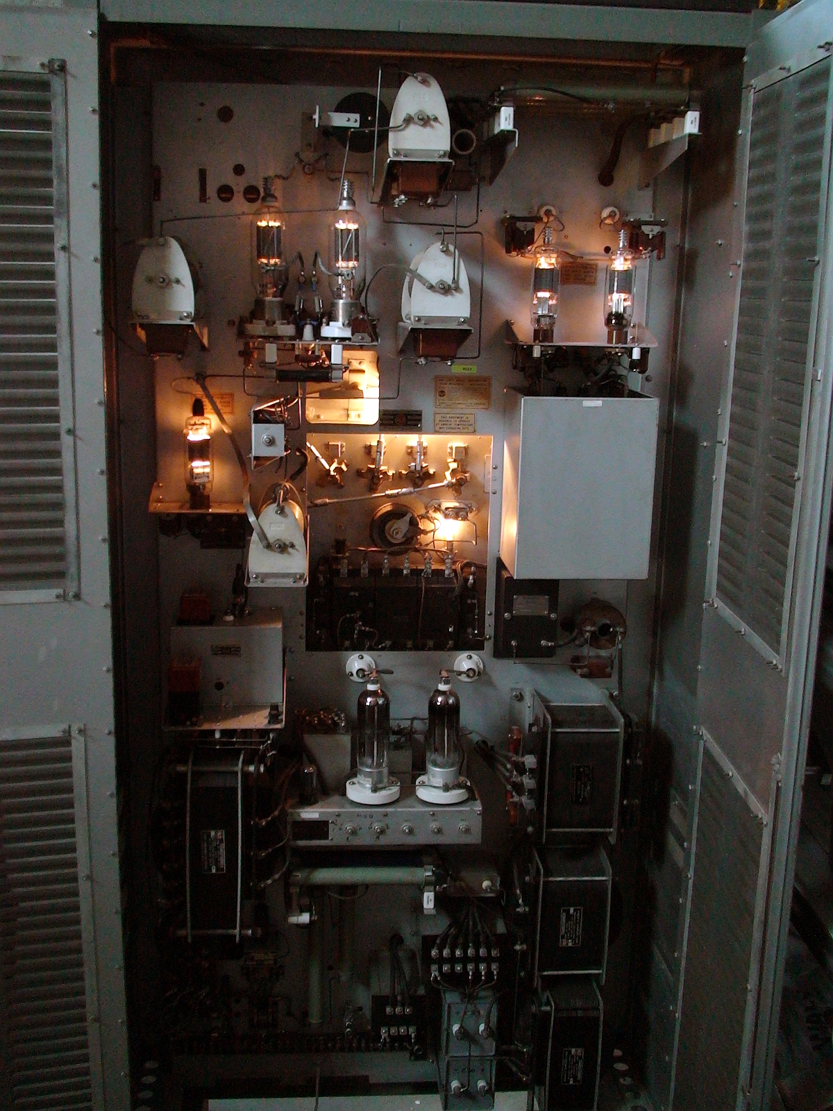
Back
View
|
-air rigs Clicking
HERE
or on the image at left brings up a larger version of the
photo |
|
Output power of 900 watts PEP was observed on SSB and a carrier output on AM of around 450 watts with only 20 watts input was acheived after careful adjustment of the input grid bias control located on the front panel. Not too shabby! Plate voltage is from a pair of 1250 volt / 250 mA center tapped transformers connected in parallel. These supply about 1900 VDC plate (1800 volts under load), and about 400 VDC screen through a series of voltage dropping resistors and 2.5H choke input from the center tap. The grid supply and relay control voltage are from a small isolation transformer with 125VAC and 25VAC respective output windings rated at about 25VA. Grid voltage stability is provided by a OC3 Voltage regulator tube. Sixty second time delay to allow for proper warm-up of the 4CX250B's before B+ is applied is provided by an Amperite 115NO60 time delay tube. |
|
Plate
Tank Inductor and Band Switch
|
Schematic
diagram
excerpt showing final amplifier and modulator electrical
configuration. See the full-sized versions linked below
for complete details. Clicking
HERE
or on the image at left brings up a larger version of the
photo |
Tube
Layout Close-up
|
Clicking
HERE
or on the image at left brings up a larger version of the
photo |
| The filament voltage is supplied by a separate filament transformer. A 10 ohm, 20 watt power resistor is placed in series with the transformer mains input to reduce high current inrush to "cold" filaments and increase tube life. Amplifier protection is via an overload relay placed in the cathode circuit of the plate supply. In the event of a short-circuit, flashover or overload condition, the plate supply is instantaniously tripped as part of the push-to-start seal-in contact on the plate supply. Overload current is set to 700mA with a very fast rise time. The antenna relay controls RECEIVER, TRANSMITTER, TRANCEIVER functions (notice there are four SO239 connectors on the rear panel, three of which are inputs, and one is output to the ANTENNA. Very handy if you happen to be using vintage equipment and don't want to have a "relay box". The antenna relay also enables/disables the screen supply voltage from the 4CX250B's to effectively reduce bias current to zero while in receive mode. All that is needed to enable the amplifier is a contact closure located on the rear of the chassis. |
|


