A TV-7 Meter Replacement Adventure
Ed Engelken
http://www.gvtc.com/~edengel/TARC.htm
Well, it finally happened! After many years of faithful service, my trusty TV-7D/U tube tester (officially an Electron Tube Test Set) started to act up. The meter pointer began to gyrate when adjusting the "line adjust" pot or making Gm readings. Further examination revealed that the meter itself was at fault. The meter resistance was variable and occasionally the meter would open up altogether. I was able to restore operation by charging up a 0.1 uF capacitor up to 400 volts and discharging it through the meter several times. The high-voltage, short-duration pulses apparently welded the faulty connection and restored operation. My joy was short lived however, as the meter opened up for good after a few weeks. I finally took the meter apart and reheated the internal connections with a soldering iron. No luck, the meter refused to work. Obviously I would have to adapt a new strategy to get my TV-7 working again.
My options boiled down to three: 1) Find a direct replacement for the TV-7 meter. 2) Find an ordinary Simpson or Triplett analog panel meter that had the proper electrical characterstics and would accept the meter scale from the old TV-7 meter. 3) Replace the TV-7 meter with a Digital Panel Meter (DPM).
Option 1 was my first choice. I contacted Fair Radio Sales as well as those fellows that advertise TV-7 repair services in ARC. I also posted a request on the Internet. The results were negative. If there were any TV-7 replacement meters out there, the owners were hanging on to them.
I just couldn't get excited about option 2. I dug through my junk box and didn't find anything promising. Checking prices for new Simpson analog panel meters resulted in "sticker shock." Boy, those things have gotten expensive!
Option 3 was more interesting. Compact, 3-1/2 digit DPMs are available for less than $12.00 from Radio Shack, Jameco, ALL Electronics, and others. These DPMs have a basic sensistivity of 199.9 millivolts full-scale and an input resistance of over 100 megohms. The decimal point position is selectable. Getting one to read "120.0" full-scale like the original TV-7 meter should be easy.
The only problem remaining was finding the specifications for the original TV-7 meter. Phasostron manufactured my meter and the full-scale sensitivity of 200 microamps was printed on the meter scale. That was easy, but finding the meter resistance was more difficult. The original meter has an internal 1.91K resistor in series with the movement. So the overall meter resistance is more than 1.91K, but how much? Digging through the Tech Manual on the TV-7 failed to yield a resistance value. Another post on the Internet produced information about the meter resistance values for the TV-3 and TV-10 tube testers, but not the TV-7. Fortunately, I kept notes when I was discharging the capacitor through the meter in my first repair attempt. The meter started out with a resistance of about 4K and after about dozen "hits" with the capacitor the resistance settled out at about 2360 ohms. That is very close to the meter resistance of the TV-3 (2365 ohms) and TV-10 (2350 ohms). I decided that 2360 ohms would be a good starting value.
The DPM I had on hand was from ALL Electronics (Cat. # PM-128 available from ALL Electronics at http://www.allelectronics.com). A quick calculation showed that a shunt resistor of 600 ohms would cause the DPM to read 120.0 for a current of 200 microamps just like the original meter. The total resistance was brought up to 2360 ohms by adding a 1.5K fixed resistor and a 500-ohm trimpot in series with the 600-ohm shunt. The trimpot provides an adjustable range from 2100 ohms to 2600 ohms for the meter resistance. This provides plenty of "wiggle room" if the required meter resistance isn't exactly 2360 ohms.
The DPM is quite thin and can be mounted on a metal (or plastic) plate cut to fit over the meter opening in the TV-7. The DPM projects less than 3/4-inch above the TV-7 panel and doesn't interfere with lid closure. The DPM requires something between 7 and 12 volts DC to power it up. The easy way is to use a 9-volt battery and a small on/off switch. With a current draw of only 1 mA, an alkaline battery should last for a year or more. I chose to use a "wall wart" for power. I found a small one that produces 8-volts DC. I mounted it on the reverse side of the DPM mounting plate and cut the AC prongs off. Wires soldered to the remaining prong studs were routed to the TV-7 power switch. A word of caution is needed here. The DPM needs an independent power supply; it can't measure its own supply voltage. So don't try to rectify and filter the TV-7 filament voltage to power the DPM - it won't work.
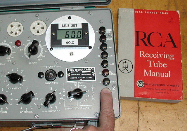
Completing the installation consisted of setting the trimpot for a total meter resistance of 2360 ohms and rechecking the calibration of the TV-7. I have been using the "digital" version of my TV-7 for the last 3 years and I must say that I like it much better than the old analog job. No more squinting to see the small divisions on the old meter. I can now make readings with the tester a full arms length away. Setting the Line Adjust pot for a reading of 60.0 is very satisfying - it just feels more precise. Of course, a setting of 59.8 or 60.1 is just as good, but I find myself tweaking it to 60.0 anyway. The extra precision afforded by the digital readout is really an illusion, but it sure looks impressive!
I believe this is the easiest, most cost-effective way to restore an ailing TV-7 with a bad meter. Your comments about this article should be sent to the author at EdEngel@GVTC.com. The author wishes to thank Alan Douglas for providing meter resistance values for the TV-3 and TV-10.
NOTE: Since this article was written, I had the opportunity to examine a TV-7A with a meter manufactured by the Roller-Smith Company of Bethelehm, PA. Both the full-scale sensitivity (200 microamps) and resistance (2365 ohms) were printed on the meter scale. With this new information it is clear that the TV-7 meter resistance is 2365 ohms, not 2360 ohms as stated in the article. This difference of less than 1/4% is of no practical consequence.
This article originally appeared in the October 1999 issue of The Lone Star Waveform, the monthly newsletter of the Texas Antique Radio Club, http://www.gvtc.com/~edengel/TARC.htm