W0OGH
250-watt Transmitter Project
Back to W0OGH Main Page
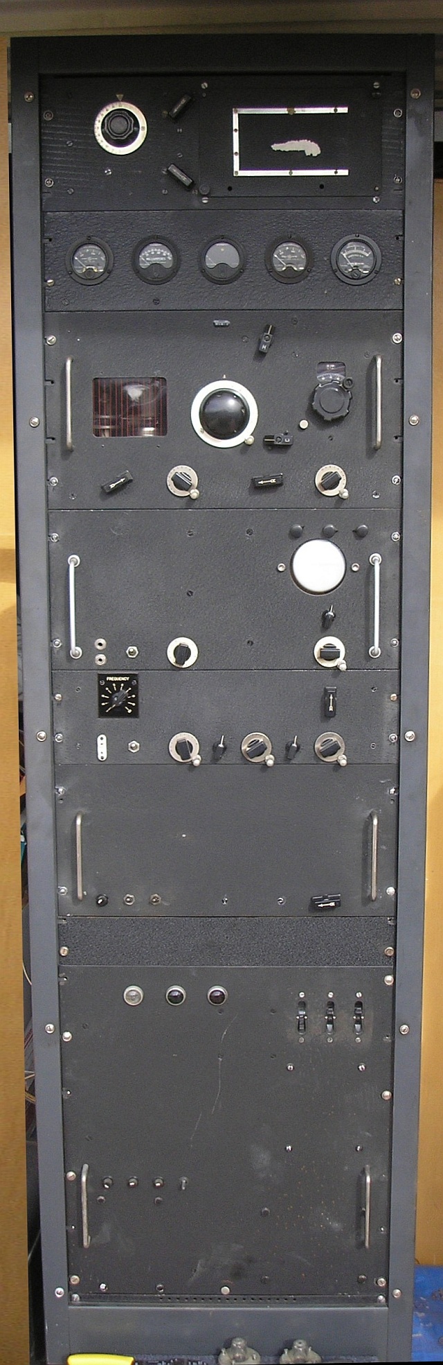 |
Larry writes: "I picked up a HB 1/4 KW AM/CW transmitter over in California about 3 weeks back. Runs a 4-250 modulated by 100THs. Real nice looking rig and well built, nothing tinny about this thing. It has provisions so that I can use it strictly as an AMP and bypass all the other stuff if need be. Working to get it ready for service as some of the electrolytics below the mod deck etc are losing their innards so need replacing, next fall when it cools off more than likely." "The wire bundles are unlaced because I had to trace out each and every wire between chassis's. It was also wired for remote control which I have to figure out and then disable so I can run it from the front with provided switches. Built-in antenna tuner for open wire or can bypass it to go straight to coax or can switch in a built in dummy load. Looks pretty heave duty. Will warm up the garage nicely this winter." The rack panels, from top to bottom, are: (1) balanced-line tuner, (2) metering panel, (3) final RF deck, (4) modulator and monitoring oscilloscope, (5) RF exciter and multiplier/driver stages (6) low-voltage power supplies and regulators, (7) high-voltage power supply and primary-power control. |
|
|
|
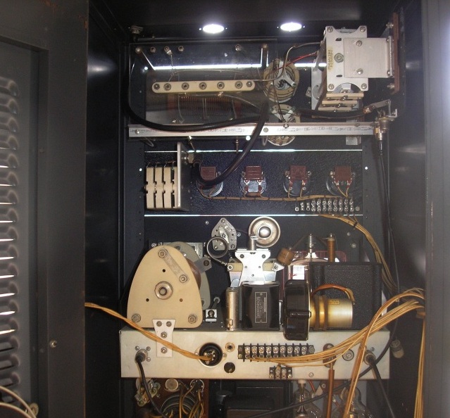 |
Rear
view of the top of the tranmitter rack. The topmost unit is the
balanced-line tuner, and immediately below it is the metering
panel. The bottom chassis is the RF deck. The plate cap of
the 4-250 can be seen to the right while the left-hand side is taken up
by the plate-tank components. |
|
|
|
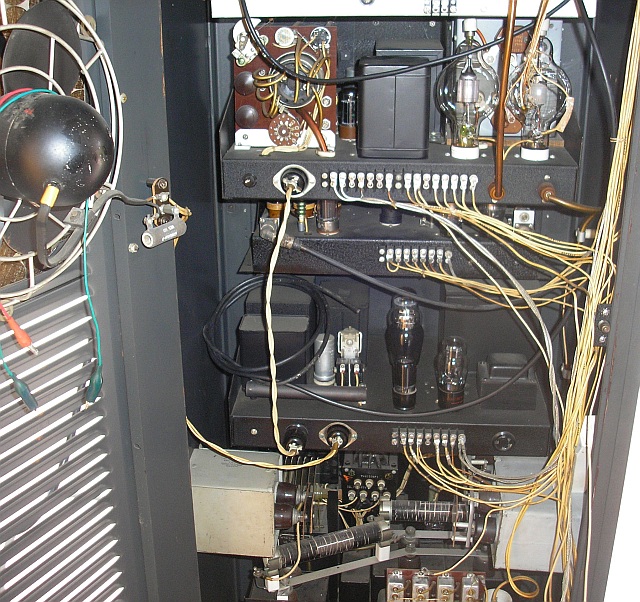 |
Rear
view of the lower part of the transmitter. The 100TH modulator
tubes are in the upper right, immediately in front of the modulation
transformer. The odd-looking assemblage on the left side of
the modulator deck is the built-in oscilloscope for waveform
monitoring. Below the mod. deck are chassis containing the RF
exciter/multiplier stages and various low-voltage power
supplies. The high-voltage supply is built into the bottom of the
rack. |
|
|
|