K0ETD QRP
Transmitter, Receiver
Back to K0ETD Page
|
|
|
|
|
|
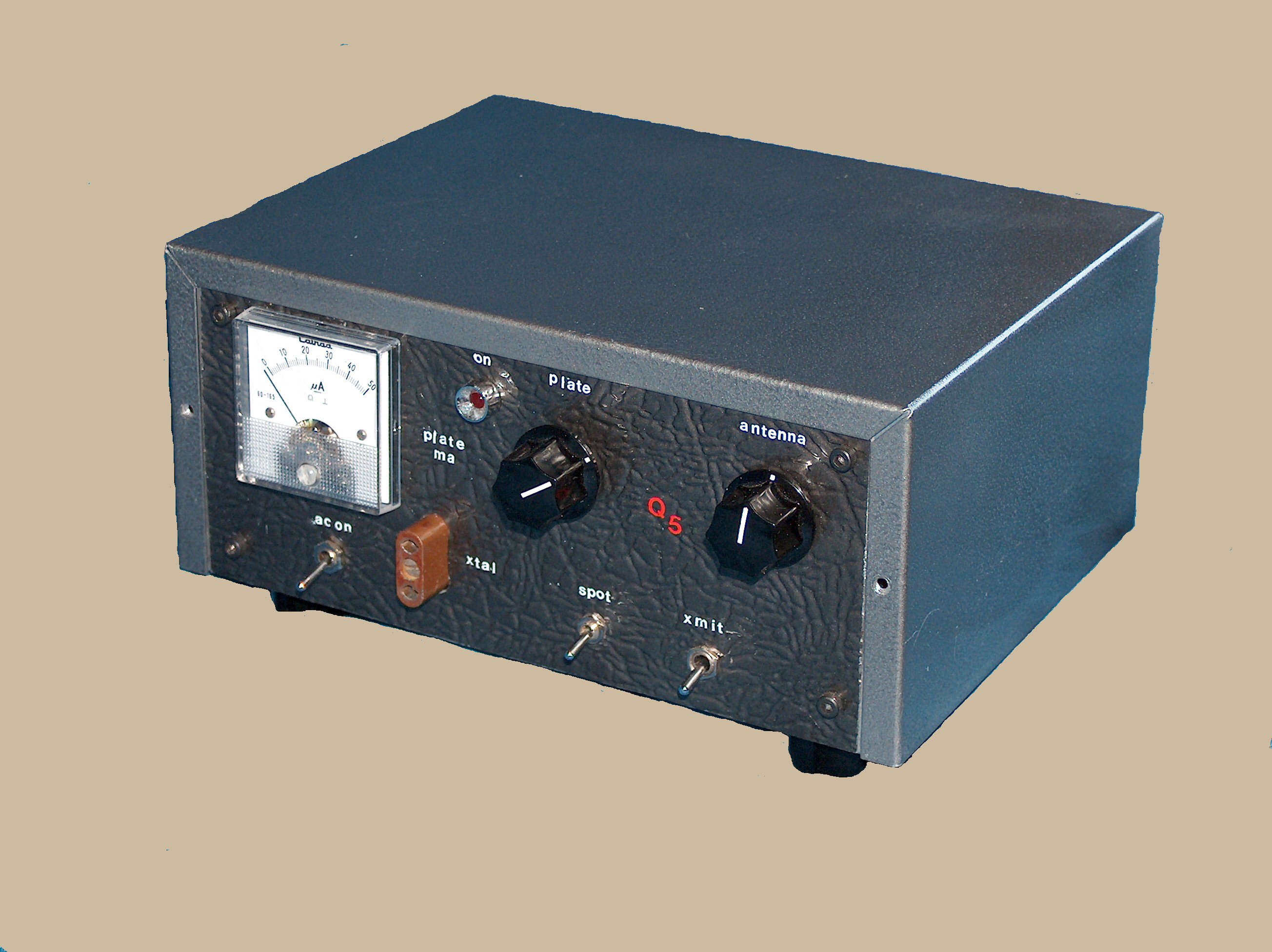
The K0ETD QRP Transmitter |
|
|
|
|
|
|
|
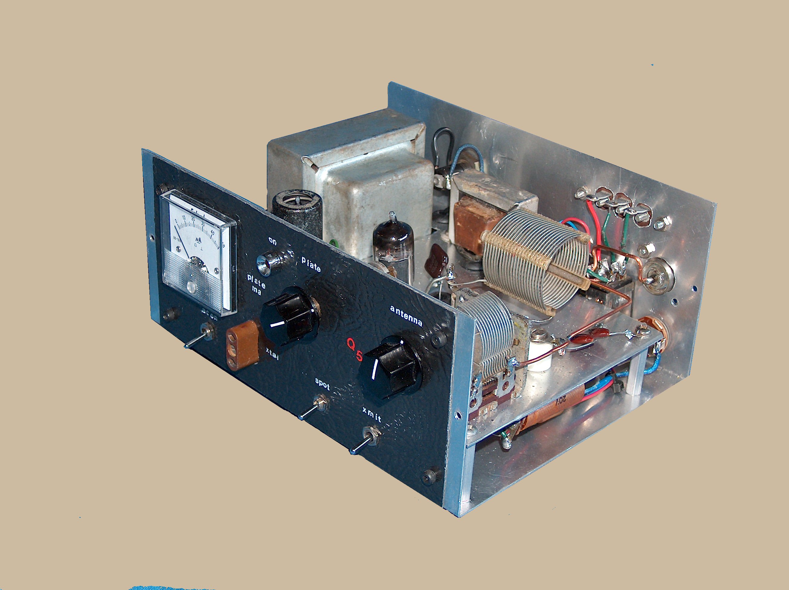
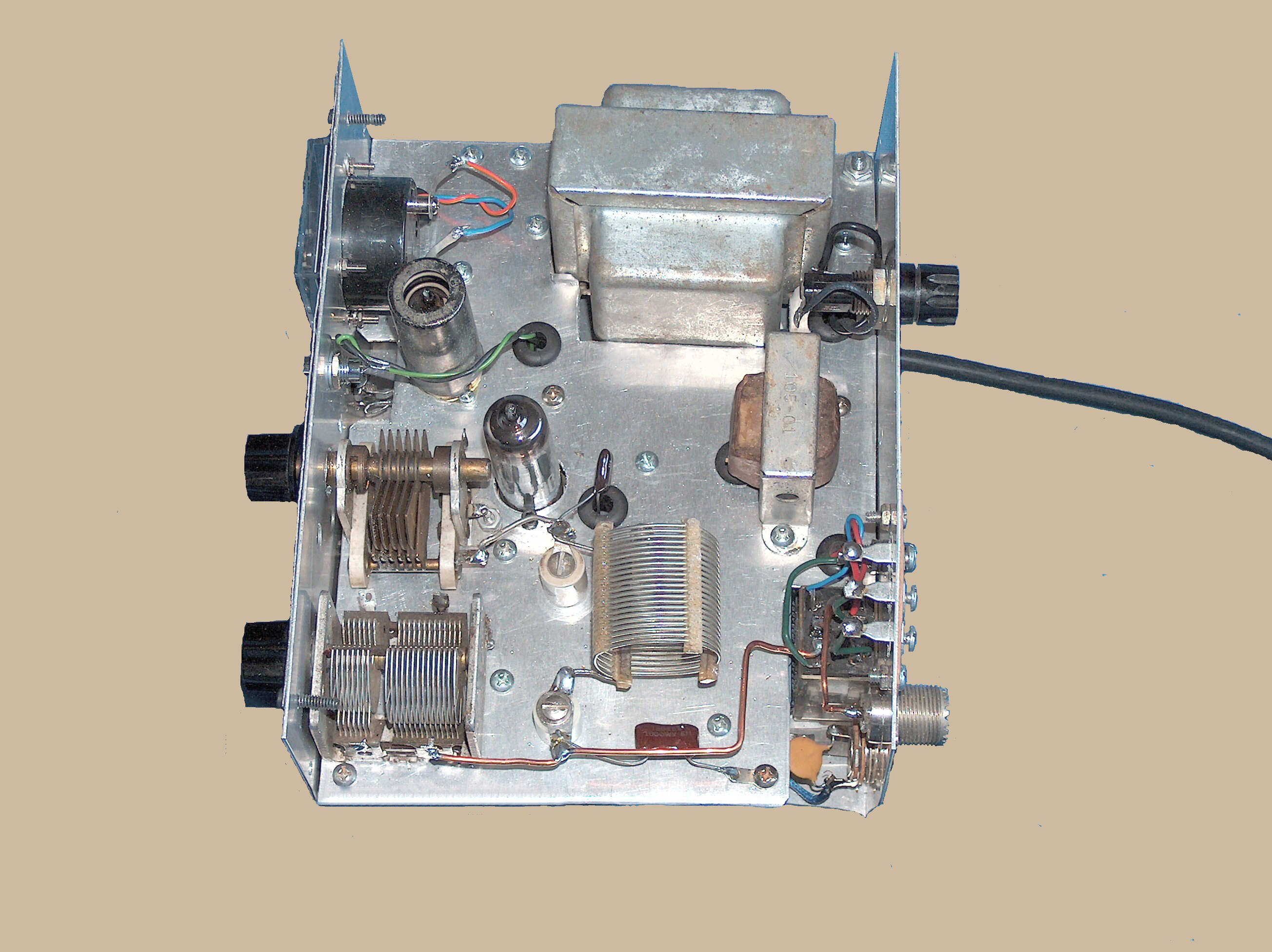
Inside view of the QRP transmitter. |
|
|
|
|
|
|
|
Top inside view showing oscillator and output tubes, pi-network output tank and HV power transformer.
|
|
|
|
|
|
|
The K0ETD 40-meter QRP transmitter is the creative synthesis of a number of stock Handbook circuits. The crystal oscillator employs a 6BH6 in a Colpitts configuration. The final is a conventional class-C stage running a 6AQ5 for 4.5 to 5 watts output through a pi network. During transmit the oscillator runs continuously and the final is cathode-keyed for a chirp-less on-the-air signal. The transmitter includes a built-in antenna T/R relay that also has provision for muting a receiver with a set of auxiliary contacts. The choke-input power supply is built around a surplus Burstein-Applebee transformer and supplies 225 volts at 30 mA to the final under nominal loading conditions. |
||
|
|
|
|
|
|
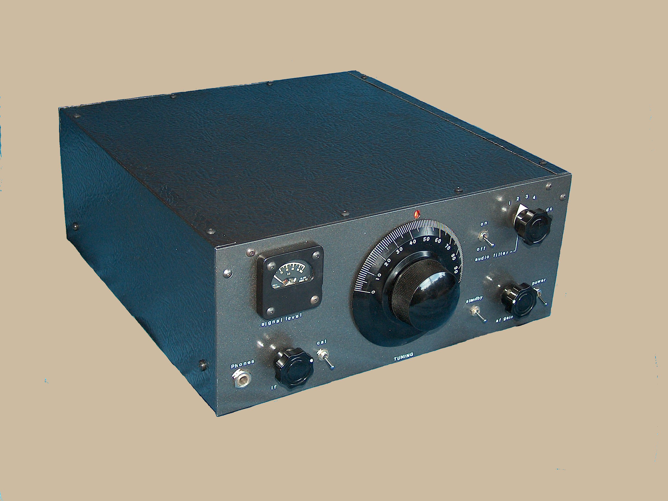
Companion Receiver for the QRP transmitter. |
|
|
|
|
|
|
|
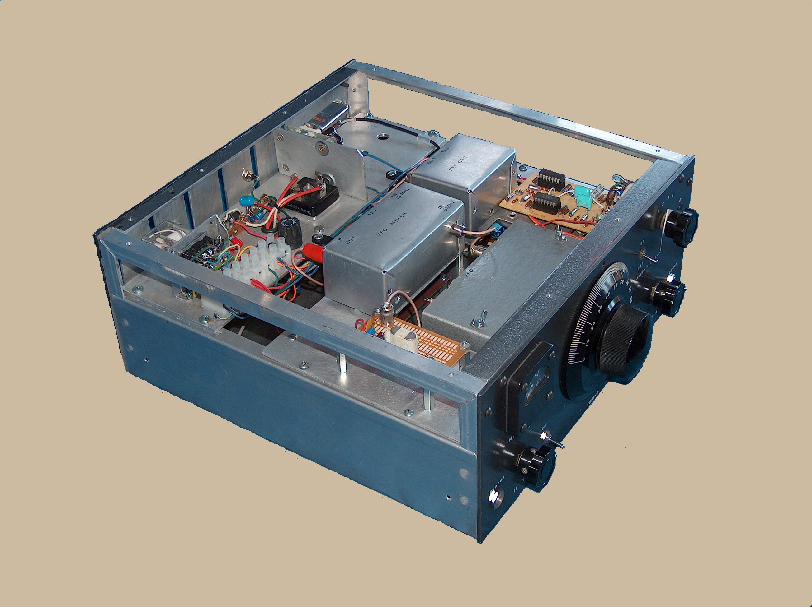
Internal view of the Companion Receiver showing shielded-module construction.
|
|
|
|
|
|
|
The Companion Receiver has been an evolving project over the past 25 years, originally starting as an SSB companion for a Swan transceiver. Its circuitry is based on numerous industry and amateur sources. Frequency coverage is strictly 40-meter CW, 7.0 to 7.1 MHz The front end is an unamplified diode-ring mixer with a tuned input similar to that found in an Atlas transceiver. This gives the receiver a good strong-signal handling capability. The 12 MHz local-oscillator drive is synthesized by mixing the output of a 5 MHz VFO with that of an 18-MHz crystal oscillator. The mixer is followed by discrete-transistor amplification and then by a crystal filter centered on the IF frequency of 5645 kHz. The filtered IF signal is further amplified by approximately 60 dB using a single MC1350P IC. A product detector implemented with a 40673 dual-gate MOSFET produces an audio signal which is amplified, fed through an active filter from Ten-Tec, and then on to an LM-383 output stage which produces 8 watts of drive for a separate speaker. The Ten-Tec audio filter, centered at 750 Hz, provides the final selectivity for the receiver with bandwidths ranging from 1 kHz down to 100 Hz. The receiver AGC voltage is derived from the detected audio and controls the gain of the MC1350P IF amplifier as well as driving the S-meter amplifier. A 50 kHz crystal calibrator implemented as a crystal-controlled multivibrator provides the means for finding band edges. The built-in AC power supply provides +12 volts to the receiver circuitry through two regulators, but the unit can be powered from a single 12-volt battery for portable or mobile operation. |
||
|
|
|
|
|
|
|
|