National Restoration Notes and Fixes


Back to Phoenix W7CPA Page

w7cpa@arrl.net

NCX-5 MKII Transceiver

NCL-2000 Linear Amplifier

NCX-1000 Transceiver 


NCX-5 MKII Restoration

I restored two NCX-5 MKIIs over the holidays and took some notes to assist others in the same geezer restoration process. My previous experience has been solely with Collins, Kenwood and Drake electron valve radios. These radios were all 1960-1970 viintage.

W7CPA NCX-5 MKII

I won't prattle on about the history of the National Radio Company or regurgitate factory spec sheets. National developed a reputation for excellence in commericial and military receiver technology.  What I observed is what I observed. See the links below for scanned images of  Service Bulletins and some fun to read, 1967 correspondence with Carl, the National Service Manager blowing smoke/BSing a good customer.

The inside layout is well done except for one tube under a shield that is a bear to remove even with the shield removed.

W7CPA  Inside

Standard Old Age (Geezer) Issues

  1. Power Supply

    Replace all the electrolytic capacitors. Measure 280vdc at the NCX-5 connector. If  it is higher than 290vdc , I suggest changing R9 from 660 ohms to 1K ohms. AC mains are much higher these days and there is no reason to push tube life.

  2. VFO Shaft Sloppy

    The fiber retaining ring for the clutch spring had broken and was pushing the shaft bushing out the front.

    I had to disassemble the gears from the bottom, removing the VFO cover.
    I replaced the washer with a nylon washer, sanded down to the right thickness.
    I thoroughly cleaned all the gears/discs/pinions and made sure all had 2 notches spring loading when re-assembled.
    I re-lubricated with sparing, light lithium grease only.

  3. VFO Display Wheel Dead Zone

    It turns out that the BAND control shaft CAM was ramming the digital display assembly too far to the right and binding the wheels. The digital display wheels must flop freely on all bands. I used the set screw and rotated the cam until all wheels flop freely on all bands. The dead zone is now gone.

  4. VFO End Points

    There is a coil and an trimmer to set end points. This is a real pain unless you have the DD-103 hooked up and the temperature compensating trimmer hoses up the works every time you make a change so end point have to be re-done.

  5. VFO Drift

    There is a documented trimmer to find a drift setting you like. I set mine for longer term stability vs. short term. It runs up 550Hz, back a bit, then rock stable. Any changes of the temperature compensation trimmer affect the low end point - of course.

  6. VFO Linearity

    The manual sort of documents how to bend the special stator tabs to improve end-to-end linearity. I gave up after 4 hours, not worth it. I got 4, 2,9, 3.8, 3.7 and 3.5 withing 200 Hz - not bad for its day.

  7. VFO Mechanical Instability Whilst Tuning or Beating Cabinet With Rubber Mallet or Baseball Bat

    I carefully cleaned the VFO tuning capacitor with special attention to the 3 WIPER fingers. I used DeOxit and sprayed away all excess. I soldered a bus wire through all 3 WIPER finger terminals and soldered the bus wire to the capacitor frame. Rivets can be troublesome in their old age, very stable now.

  8. Local Oscillator Trimmers

    After the VFO is the best it can be on 75 meters, go to each band and adjust the appropriate trimmer for the same dial setting. I could only get within 500Hz but that just fine. If you don't have a digital display, you can attempt to follow the instructions in the manual.

  9. Transceiver Vernier (RIT) Instability

    I added a ground wire from the RIT potentiometer to a new GND lug on the chassis to eliminate the poor path through the front panel.

  10. S-Meter Zero Drifts

    It takes about 5 minutes for the S meter to drift down to the proper ZERO setting. I attempted no fix for this - maybe a componenet change somewhere.

  11. 40+ Years of  Grime and the Magic Feather

    Clean with a neutral cleaner. Alcohol can damage geezer painted items. A mid sized pheasant or guinea fowl feather makes an amazing digital display wheel and grass cleaner - no disassembly required. They are curved just right and have little dusting feathers at the ends.

  12. Aluminum Knob Inserts Randomly Fall Out

    Clean and reattach with clear silicon adhesive. I had one that cracked down the side that epoxy fixed pretty well.

  13. Calibrator

    This radio really needs a crystal calibrator due to the VFO linearity irregularities. I am going to explore a modern solid state version I can plug into the socket.

  14. Crackle Noises in AF During Warm Up

    I suspected the multi section (40uf, 40uf, 20uf) can capacitor. I have one ordered from www.tubesandmore.com and will report on the final outcome. The new capacitor solved the problem. It measured ok but must have been breaking down from time to time. 


Design Flaws and Some Suggested Fixes/Improvements
  1. Does not Transmit and Receive on the Same Frequency
The original design has insufficient VFO buffering to handle all V3 tube characteristics changes. The only fix is to swap V3 until you find a tube that works. It took 4 tubes to get the XMT-REC delta to < 10Hz. It ranged up to 110Hz and National thought 50Hz was in spec! If anyone has a better idea, please post it. The voltage regulation has NOTHING to do with this frequency delta - it's the huge load change on V3. I even tried a high quality 3 legged voltage regulator to no avail. Use only NOS tubes for this exercise. 
  1. Annoying 1,800 Hz CHIRP-YELP in the Speaker on SSB PTT/MOX and First Key Down on CW
On AM and VOX mode the problem does not exist.
Some units do not have the problem.
I suspect that the TR relay drop out speed and physical contact spacing just happens to be fast enough to mute some units.
The goofy design pulling in the relay for RECIEVE provides a sure thing, long time magnetization behavior change factor.
If you have this chirp try adding a reverse diode across the TR relays coils. I have heard that this sometimes works to reduce the big inductive spike.
This did not fix mine, Mr. ugly lived on.

The chirp (ugly 1800Hz triangle wave) is being generated by the LOCAL OSC tube, primarily on 75 meters when it is not oscillating - no crystal or trimmer between plate and grid, etc. The chirp gets fed into the V13 mixer grid when the TR BIAS changes all XMT tube bias points. The chirp is only approx 25 msecs but damn annoying, especially if the AF gain is up on weak signals.

If the AF stages were muted properly, no one would care about these transitional glitches.

The PTT/MOX design sequence is all wrong and relies on the DROP_OUT speed of the relay which gets magnetized over time since it must be pulled in for receive mode – this is odd in itself.

The unfortunate sequence that allows the annoying chirp to sneak in is as follows:

1.    PTT/MOX/FIRST-KEY closure to ground
2.    TR BIAS (135) gets grounded.
3.    This changes all XMT tube bias points for XMT mode. This is where chirps and other weird transitional crap happens.
4.    V3’s screen voltage drops and a BIAS CONTROL voltage divider develops -40vdc REC BIAS.
5.    This -40vdc is sent to the PPT DIODE to drop out the TR RLEAY and mutes the PROD DET and AF at the same time – TOO LATE BINKY!

The possible fix scenarios were.

1.    Redesign the whole XMT transition process. This would be pretty invasive.
2.    Change the design to work like VOX mode (use the TR relay for bias changes, muting etc.) This too would require cuts and hacks.
3.    Install a reed relay to disconnect the speaker.
4.    Design a clever solid state switch to overlay the current design and always mute the PROD DET and AF before all the goofy XMT bias transitions happen. This might not require any wire cutting or hacks. When the TR relay opens and mute happens again - WHO CARES, AF land is already muted.
5.    Take the NCX-5 to desert and make it pay the price of its dishonor ability with FMJ 5.56 NATO rounds. The chirp was starting annoy me big time.
6. Figure out a way to dampen/choke the LOCAL OSC and the SSB CAR OSC to snuff out all chirp-like crud. I spent too much time on this option and gave up like I suspect National did in the 60's.

The Fix – Option 4 Chosen

With inspiration from WA6TJN and a cool little MOSFET switch designed by K7JEB, a reasonable solution is at hand. I have tested it in all modes for days now. NCX-5 operation is a real pleasure now. The only XMT transition noise is a small thunk - no longer annoying.

The following picture shows the prototype board with an overkill 12amp MOSFET and junk box resistors.
W7CPA Chirp Fix Board
       
        The final version with 1/8 watt resitors and the small VP0550 MOSFET.
W7CPA Chirp Fix Board
The schematic is quite simple. The parts list is small (1 MOSFET, diodes and 4 1/8watt resistors, 1” by 1” Radio Shack perf board, Velco. It connects to 4 points with no wire cutting: -80vdc, GND, PTT/MOX (135), AF-DET MUTE(131).

W7CPA Chirp Fix Schematic

MOSFET Data Sheet

The chirp fix  board was Velcro mounted to the back side of the SSB OSC shield and the 4 wires run - no cutting required. You can zoom in on the image below and follow the white wires from the fix board to see the connection points.
W7CPA NCX-5 Bottom
  1. AGC too Fast for SSB

    Older SSB rigs tended to have faster AGC than I like to hear. I  changed C146 from 0.1uf to 0.2uf.

  2. S-Meter Not Accurate Above S-9

    Over S-9, this puppy is way too generous. This is usually old caps and resistors but I think it's designed this way. No fix.

  3. CW Note Still Poor After Applying Service Bulletins

    The transitions are just too large for the OA2. I might try supplying the VFO 6.5vdc from a more isolated supply off of the filaments with a 3 legged voltage regulator - some day.

  4. Modern VFO Stabilizer - X-LOCK

    I've wasted hours tweaking the temp-comp trimmer for best behavior and there is a limit of reasonability. I hate the continued small drift even after a hour warm up. I adapted a modern, microprocessor controlled stabilizer X-LOCK. This puppy keeps the VFO within 10 Hz - smoking !!! It is a brilliant new design based on older "Huff-Puff" designs. See the extremely well written manual for additional details X-LOCK Manual.

    W7CPA  X-LOCK SCH

    The External VFO is perfect for this enhancement. The VFO is powered from the 280VDV line using 2 series panel lamps, a 18v zener, another series current limiting resistor and a final 6v zener to supply the VFO transistors - weird. If the panel  lamps die, the VFO dies plus the lamps get very hot. I initially tried a 12v zener with a 5K 20 watt resistor but this is a stupid waste of power and another heat generator. I found that a simple rectifier and cap off of the 12VAC line made more sense. The 3 connections are: 12VDC (diodes and cap on J2 pin 7), VFO output to sample from (on terminal board coax connections), simple varactor diode network inside the VFO can with short leads using the handy 2 empty termial lugs.

    I used a 12pf coupling cap instead of the supplied 22pf to eliminate warble and still have the required varactor steering range from cold to hot. I programmed the "post tuning delay" to 10 seconds vs. the default 2 seconds. This gives one time to get precise with the clunky mechanical tuning mechanism before it locks down. The RIT logic is just a minor annoyance when setting the dial within 10Hz. The RIT is not operational when one is using the National External VFO. Just turn off freq quickly, 2-3KHz then set for precision.
    Note: you will have to recalibrate the VFO end points - arrrrgggg!

    24 hour longer term testing shows VFO output is held within 20Hz.. This exceeds the designer's specifiication and makes me smile. Without X-LOCK my VFO drifts 300+ Hz from cold to hot. This was very good for 1967 mind you.

    W7CPA  VFO Mount 1     W7CPA VFO NET     W7CPA VFO MNT2
10 Hz Resolution Modern Digital Display

The DD-103 Digital Frequency Display from Electronic Specialty Products in Florida works well. Since he has no NCX-5 pre-programmed offsets, it's a real challenge to program but it works very well. Unlike the DDF for Colllins, you have to manually change bands and modes since the only input is the VFO signal. Programming involves defining the offsets for each band and mode. I sent all the offset data to the manufacturer and perhaps he'll add to the pre-programmed selections for both the NCX-5 and NCX-1000.
W7CPA dd-103

Operational Experience
Service Bulletins
1967 BS from a National Service Manager Denying the Design Defects

Brochure

NCX-5 Transceiver  Manaual

NCX-A Power Supply Manual

Excellent National Products Link to Radio Bay (W0VLZ)


NCL-2000 Restoration


The NCL-2000 I acquired is not in the near new condition the NCX-5 MKIIs are in - lot's of chassis discoloration - fugly but not material. In spite of my fine and noble plans to the contrary, I made the mistake of powering it up to see if it played before going through it.

The power supply and tubes were in reasonable shape because it was making 1,300 watts output (the factory rating) on 75 meters. This is NOT a 1,500 watt PEP amplifier. My NIST calibrated power meter shows 1,300-1,400 max with new tubes. 1,300 watts out  is pushing two 400 watt tubes quite hard but effectively.

The documented tuning procedure is the most arcane I have ever seen. There is no microprocessor control of anything. Take to time read the lengthy CW tune up procedure and do not deviate from it. I supply enough drive in CW mode for 600 ma plate current and 10 ma screen current. One can then switch to SSB mode and operate at full power without any additional tuning. This is not bad once you get the hang of it.

W7CPA NCL-2000 Front

On Christmas eve, I was testing the hanging TR relay problem, trying a few difference bands etc. I accidently rotated the MULTIMETER switch  from SCREEN to EXCITER TUNE with exciter drive still on. A very large explosion happened with flashes of light coming out of the rocker switch cracks. This kind of explosion usually indicates an RF deck/DC voltage issue.  Both 12 amp AC mains fuses were vaporized.

The manual has a notice buried in the ALL CAPS paragraph warning about trying to tune into bad loads. The "MULTIMETER" switch has a non-multimeter position that can be a killer. It should have been a stand-alone warning in large, bold type. Something like the following would have been handy:

In general, make it habit never to change any BAND switch position or transition in/out of "MULTIMETER" - EXCITER TUNE position with the PLATE voltage ON. If you do this and you have any exciter drive present, major league internal damage will occur.

Hoping the now rare RCA 8122 tubes were not toast and the bang bang was only associated with the primary side,  I put the amp on the bench. All of diodes and capacitors were ok in all power supply sections (this is goodness so far). The only explosion evidence was the carbon-burned PLATE RELAY contacts. The contact pads were burned bad enough that I needed to replace K3 for sure. The prior cap replacement job was so poorly done, I decided to rebuild everything on general principles to remove the fugly factor.

Repair Summary - First Pass

  1. The explosion damage was fortunately limited to the PLATE RELAY (K3) and the HV secondary lead that must have been hanging by a thread and got blown off. I replaced K3 with IDEC RR3B-U-AC12 , leaving the plastic cover on, all caps, resisistors, and diodes as well as the broken secondary connection on the HV board. It looks nice and works now - no smoke escaping!
W7CPA NCL-2000 Bottom
  1. The TR relay hangs at random. I tried a heavy duty degauser for grins (heard rumors about this possible fix), no luck. I am pretty sure the contacts were burned down and sticking vs magnetism related. I burnished/sanded the contacts and replaced the weakened relay spring with the stronger spring from the fried PLATE RELAY with limited success for only a few days. I had to replace with an IDEC RR3B-U-AC12 not-quite-the-same replacement - it barely fits but is high quality.
  2. I replaced the 8122 anode parsitic chokes with a Rich Measures ("voodo") choke set. Two 3W 100 ohm film resitors with 6 turn nichrome wire, 0.25in coils. This did not work well as Carl warned. In the end,  I changed to the National recommended design.
  3. Grounded cathodes - I might move to 12-25 ohms next time I open it up to reduce distortion, should not be at ground potential, found an unsoldered pin 4 on one tube - a factory inspection flaw.
  4. WARNING - the time delay tube does not time properly when hot.  The 8122's require 60 seconds of warm up. I've observed 40 seconds when I power off and back on quickly.
  5. Lid interlock switch intermittent - the 2 prong lid plug inserts into very sloppy receptical on the chassis. Mybybe heat has caused this over time. One would not think this simple arrangement would fail but mine did. The symptom is the PLATE light would not stay on after depressing the PLATE voltage rocker switch. I bent the prongs out a bit and sprayed with DeOxit to solve the problem.
  6. The aluminum knob inlays were tarnished. I tried some aluminum cleaner with less than stellar results. Any ideas would be greatly appreciated from the National restoration community.
  7. I replaced the 8122 anode parsitic chokes with a Rich Measures ("voodo") choke set. Two 3W 100 ohm film resitors with 6 turn nichrome wire, 0.25in coils. This did not work well as Carl warned. In the end,  I changed to the National recommended design.
  8. I replaced the 8122's with good looking eBay pulls for $55.00.
    I thought that RCA and Burle were the only 8122 manufacturers. I just purchased 4 NOS Eimac 8122s on the 40 meter swap net - real beauties. I also bought one  NOS Burle - dripping with tubes now! The two I installed are almost perfectly matched and I have seen short peaks on 1,500 on 75 meters but there is no reason to run them that hard. The difference between 1,300 and 1,500 watts on the receiving end is negligible.

    W7CPA RCA 8122
                                             RCA 8122 Data Sheet

W7CPA Eimac 8122

Repair Summary - Second Pass

  1. I replaced the anode parasitic compressors with the ones designed by the National Service Manager (QTY 3 120ohm metal film 2 watt with 1in loop). I am now going to redo using old school, carbon 2 watts since these modern metal film resistors don't like 15 meters - no doubt minor inductance added.

    W7CPA NCL-2000 Parsitic

    W7CPA NCL-2000 top

  2. I installed two nearly new, matched 8122's. The Eimacs seem to require  less drive.
  3. I cleaned all band switch contacts and discovered wipers some are burned. I heard that OAK made these switches and have some on order from Surplus Sales so I can replace the burned wipers. Hobby Bench has some nice little brass nuts and bolts to replace the rivets. Thee tank coil and swiitch can be removed as one piece to make the tear down a little easier. On closer inspection, It looks like some wiper repairs have been made in the past.

    W7CPA NCL-2000 BS


    W7CPA Coil Removed


    W7CPA Coil Mount

    I ordered some old 2" ceramic OAK switches from Nebraska Sales for parts. It looks like someone has already done one wafer repair and did not use proper silver wipers or brass bolts - sloppy and not optimal for sure!

    W7CPA BS Before 
After careful rebuild with Hobby Bench 2-56 brasss bolts and nuts plus real silver wipers from Nebraska sales WWII OAK ceramic switches, I'm ready to re-assemble the beastie. The blue is LockTite on all bolts.

 W7CPA BS After


The End

Final top view after band switch fixes, new Eimac tubes,  more cleaning of tarnished chassis and a new TR relay.

W7CPA Top After

Final, final version with olde school 2 watt carbon resistors in the anode chokes, now DONE !

W7CPA Old School Chokes


NCX-1000 (the Beast) Restoration

The NXC-1000 was the last transceiver National produced prior to going out of business. So far, its performance is pretty impressive. It's roughly the size of the NCL-2000 linear amplifier and almost as heavy - a manly radio for sure! It is solid state except for the driver tube and the ceramic 8122 (same tube as the NCL-2000). In reality, it was a prototype that slipped into production status before it was ready. Unlike Collins designs, field maintenance was never seriously considered. The output is 500-600 watts PEP (depending on mains voltage) and has zero final tube protection outside of the human operator. Monitoring plate AND screen current is absolutley manditory to avoid toasting the 8122.

NCX-1K Front

Block Diagram

W7CPA Block Diagram


NCX-1K Top    NCX-1K Botton    NCX-1K Back

Warnings

Safe Initial Transmit Path Testing

The following sugggestions were learned the hard way.
  1. Remove the B+ and 8122 final - most initial testing should be done with  no B+.
  2. Check that the PLATE SW is OFF and power ON. 
  3. Now check all the  low voltage supplies are OK, changing with the TRANS/REC SW as noted - see page 5-8 in the manual. All the colored wires on the bottom IF card are handy test points.
  4. Power OFF.
  5. Remove the cover on the bottom to get at the 8122 tube socket.
  6. Get a DC meter ready because the tube will overheat without the airflow. Never go for more that 120 seconds or pull the 8122.
  7. BIAS/ALC Quick Test
a) Power ON
b) In SSB receive mode measure the following by flipping the TRANS/REC SW.
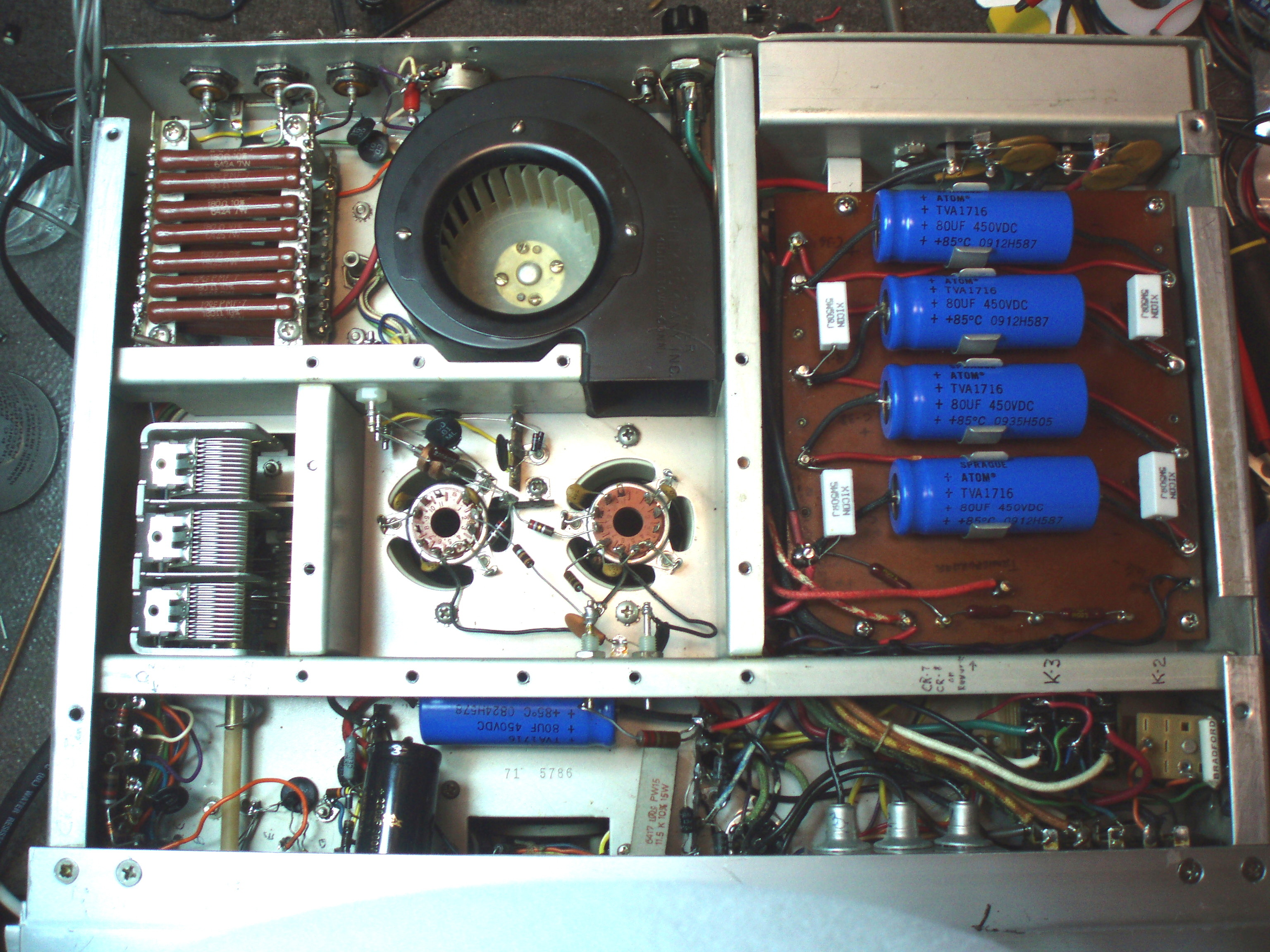
- Driver tube pin 2 (REC = -15vdc, TRANS = 0vdc
- 8122 8,9 or 11 (REC = approx -70vdc, TRANS = -30vdc with the bias pot half way.
If these voltages are good, the BIAS/ALC board is OK. Q203 and the input diodes are OK and it's safe to try an 8122.
  1. Now make sure that the driver tube pin 2 has a nice looking SSB signal on it as you talk and has a magnitude of at least 2 volts RMS. You will have to carefully apply B+ to get a good waveform.  If there is no or low signal value on pin 2 then there is a problem in the preceding solid state stages. Be VERY CAREFUL tuning the coil slugs. They are very poor quality/old and this is how I ruined the BP FILTER on the 1st IF board.
  2. Install the 8122.
  3. Power ON taking care the PLATE SW is off and wait 30 minutes if the tube has been sitting for years. If you power up with an old tube and B+ on, it will destroy the tube most of time.
  4.  Meter on Plate V, PLATE SW on, watch meter and be ready to turn off quickly of the plate voltage is not stable around 3,000 vdc.
  5. SSB mode, MIC level full CCW, bias pot on back set to the middle.
  6. Meter on plate current, quickly flip TANS/REC SW to TRANS and be ready to turn off quickly if not around 100-200ma. If it pegs to the right and blows the .5amp fuse, you might have a bad tube and damage might have been done to the 680 ohm resistor and parts on the BIAS/ALC board.
  7.  Normally, this is where you set the bias on the back to 80-100ma when keyed in the SSB mode.
  8.  Tune up is weird and you must carefully set the loading control to not exceed 10ma of screen current at max power out. On my bench and a BIRD wattmeter I am getting 600 watts out in the TUNE mode. At my operating position I only get 400 so I think I have a crappy wall outlet to investigate. I dip the plate first and then go to SCREEN to peak the screen current land limit it to 10 ma. Max power out is where the screen current is peaked.
  9. A good place for a 200VDC MOV is on the little terminal board before the RF choke heads off to the 8122 grids through a 2.7 Ohm resistor. This should help mitigate futer 8122 failure damage.
  10. If you have blown the 0.5 amp grid fuses many times, be sure to check that the 680 ohm grid resistiors are not damaaged. They are in // to ground so they should read around 340 ohms.
Rock on!