Globe 500C: Article I wrote in hopes of saving a ham some time:
I wanted
to make a post in hopes that someone down the line would search and
find this information useful in restoration of a Globe King 500. Many
of you have helped me and know the story but I would thought it would
be worthwhile to type up some documentation for the group.
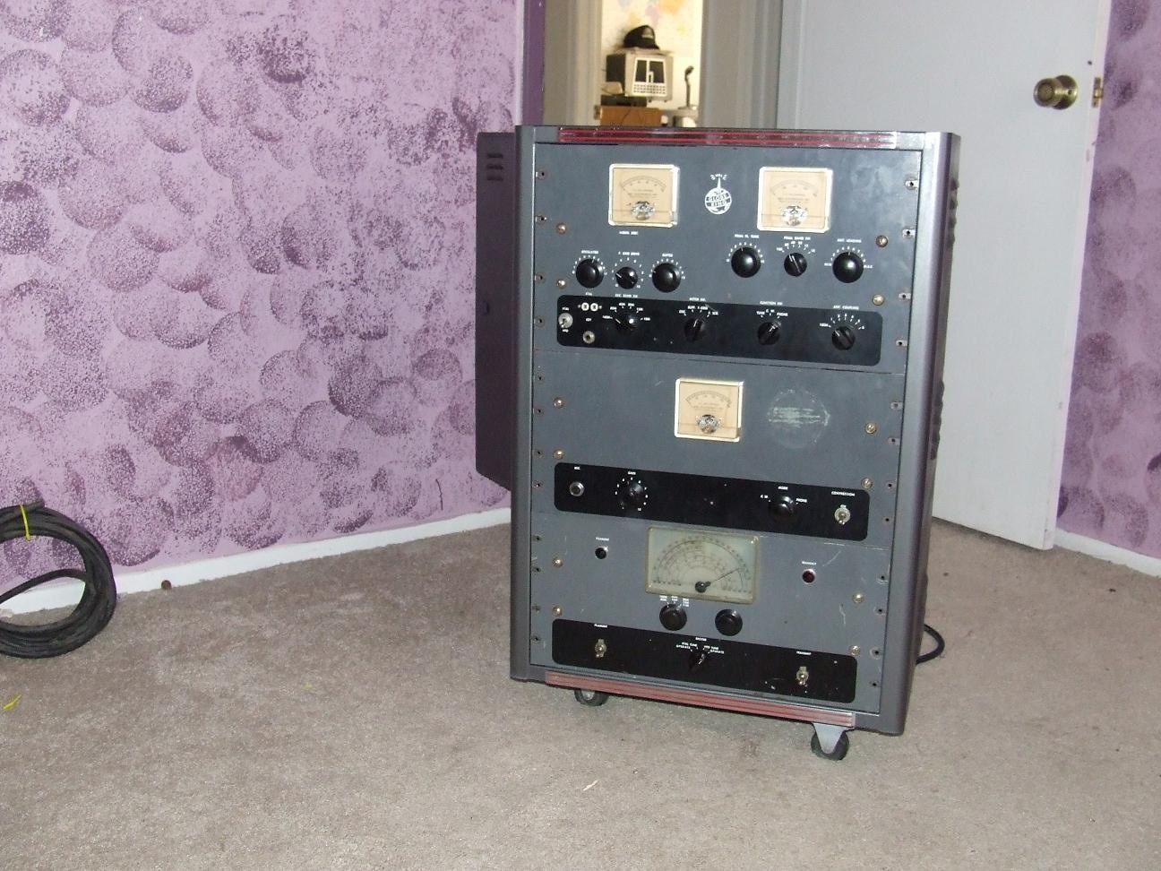
My Globe
King 500C was not working when I purchased it. The owner before me
installed the wrong tubes in the modulator rectifier sockets. This sent
AC voltage through the mod deck.
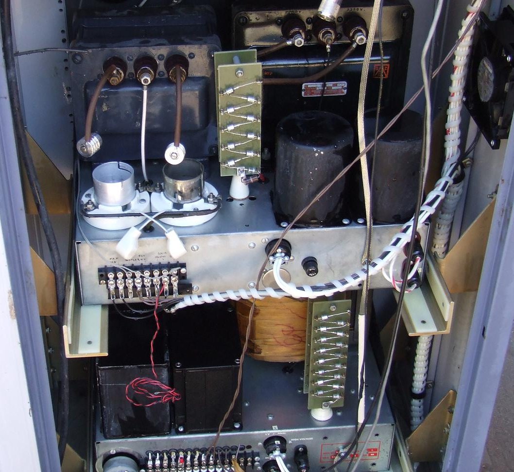
Modulator:
1. Every tube in my deck was bad. The 811s were shorted. New tubes installed.
2. The HV
power trans for the modulator deck was shorted. I got a used one from
W0VMC, Robert. W8QBG, George, came over to my house and helped me wire
it in.. What a guy!
3. I converted to Solid state plug-in rectifiers. I now have 1600 Volts on the 811s.
4. Replaced all old capacitors with higher values.
5.
Performed the W0VMC Modulator Speech amp kit. Kit came with
Schematic and all parts for hi fi audio. No more couplates.
6. His mod also allows me to use the Phone patch cable with external audio gear, bypassing some of the preamp tubes.
7.
Replaced HV connector on back. Used to have old standoff types. I used
screw-on Amphenols from Henry Radio with spark plug cable.
8. Cleaned switches and pots with Deoxit
9. PTT was
not working. Found that the electrolytic near the selenium rectifier
was bad. Replaced cap and used 1 amp diode in place of rectifier.
10.
Replaced 6 uF oil-can cap in HV section with a new 12 uF from W0VMC
Robert. It fits in, I had to extend the clamps with custom made
brackets.
At this point The mod deck was up and running.
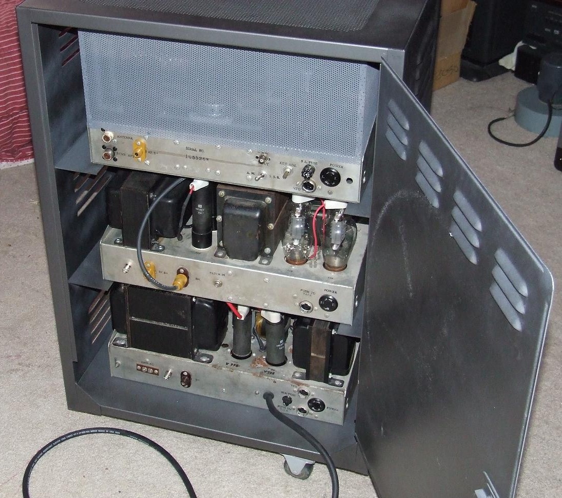
Power Supply Deck:
1. Cleaned chassis
2. Cleaned relays.
3. Replaced 866s with plug-in, solid-state diodes.
4. Replaced Broken 866 plate caps.
5. Replaced cracked power cord with large-sized cable and large, high-amp plug.
6. Replaced various paper caps.
7. Replaced high-voltage standoffs with Amphenol screw types from Henry Radio.
8. I had a
burned relay contact on the PTT relay. I unscrewed the contact "stack"
and flipped them so I had a new contact in use.
At this point, the deck was now safe and working.
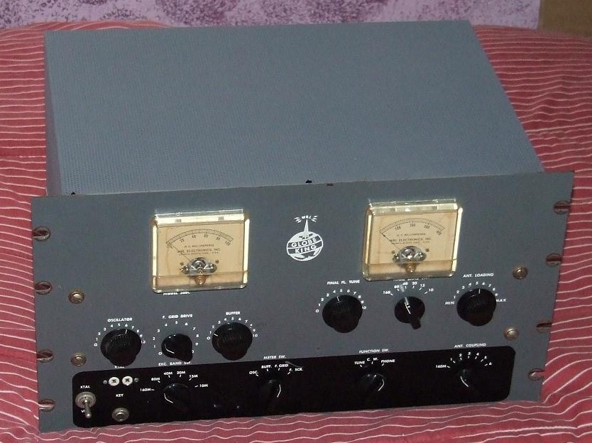
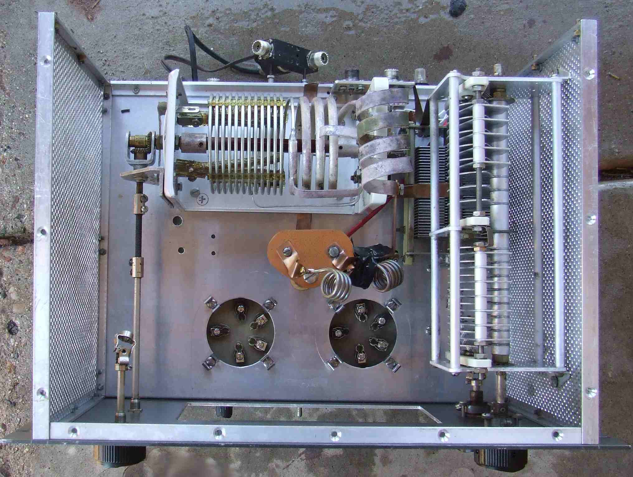
RF Deck:
1. Replaced all paper caps in screen supply and throughout the deck.
2. Found cracked 500PF doorknob cap. Replaced with 1000PF unit.
3. Found burned parasitic resistor on 6146 and a dead tube. Replaced both.
4. Cleaned tank coils with Tarnex metal polish.
5. Replaced the screen rectifier tube with new one.
6. Found one side of the 12AX7 dead. Replaced with new tube
7. Replaced screen bypass cap with silver-mica block-style cap to ground 1000PF (w0vmc mod)
8. Replaced filament bypass caps (.005's) with .01 large-diameter caps to ground (W0VMC mod)
9. Cleaned switches and controls with Deoxit.
10. Replaced HV standoffs with screw-on types from Henry Radio.
|
|
As you can see, This was a basket case. After getting the rig up
and running I found I could not load to 330 MA. I could reach 280 to
300. Power output was about 250 to 290 watts AM on a Bird 43.
I had one melt-down about a month into using the rig.. The 6CB6 tube
shorted. This is the VFO buffer tube that drives up to the RF deck.
This tube caused the solid-state diodes on that supply to fail. A new
tube and a 5R4 plugged in got the rig back up and running.. Now I can
load to 330MA. It's imperative that the VFO has enough drive or
you will never get full output. Check or swap the 6CB6 tube and the
6AU6 tube out with others until you can reach 330ma. Power output
jumped to 340 to 350 watts AM after this, at 330MA.
Later, I changed the 4-400 bypass caps. They are WAY to small for the
job. They used tiny little disk caps. Mine where dark in color from the
heat. W0VMC told me to change them and it made a big difference in
power and audio response just as he said it would. Now, with the .01s
on the filament and the 1000 pF mica on the screens, power output is
375 watts at 330 MA. If you turn the Grid Drive up a bit it will do 400
easy. I run it around 320MA at 350 watts with a grid current of 15 ma.
It's important to go back and tune the Buffer knob for max plate
current. This is stated in the manual. If you forget this you might be
leaving some power on the table.
I run my Globe King 500C on a separate 30 AMP wall box with number 6
cable to a 30 amp breaker. This seemed to really help. The standard
wall socket is not enough really. At least not in my house. Very stiff
supply and it shows in my output.
I run a Behringer 802 mixing board.. Cost $69. I also run a
Marshal MXLV57M large diaphram condenser microphone. This mic. requires
48 volts from the mixer. This caused me to buy the 802 mixer. The
Drawback is that the 802 DOES NOT have a high-impedance output. It has
the 1/4" jacks but in the manual it states those are 150 ohms out. This
resulted in low audio. I purchased a low-to-high, impedance-matching
transformer and a right-angle, 1/4-inch plug. This matched the 802 to
the high impedance input on the modulator deck. Just buy a mixer with
high impedance out.
Future mods? The only thing that stands out is the HV,
oil-filled, can capacitor. It is only 4 uF. I woud like 10 to 12 uF in
there and at least 3 people told me to get at least 10 uF. I have
purchased some 10 and 12 uF caps and will try to get one of them in.
Results:
When swept at the mixing console to the modulator deck with 20 Hz to
20,000 Hz, the audio is flat from 20 Hz to 9000 Hz. It's 3 DB down at
10,000 and past 10 it rolls off hard. Not bad!
Power output is now 375 watts At 330MA. Modulated 100% it actually goes forward to 400 RMS on the bird 43.
Many, many people on the boards have helped me. I am very grateful for
all of those who have helped! Hopefully someone will come to this
site with a Globe King 500 that needs a list of things to check and
this post will help! I am no expert.. I have basic skills. Many of
these people where very patient with me during this project!
KE7TRP
Clark
|