SECTION FOUR
GLOBE MASTER 4-1000A RF DECK
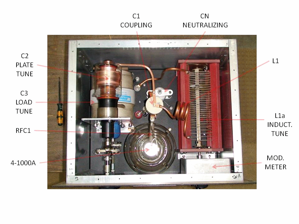
RF DECK TOP VIEW

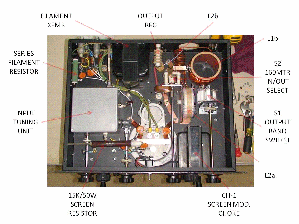
RF DECK BOTTOM VIEW

RF DECK
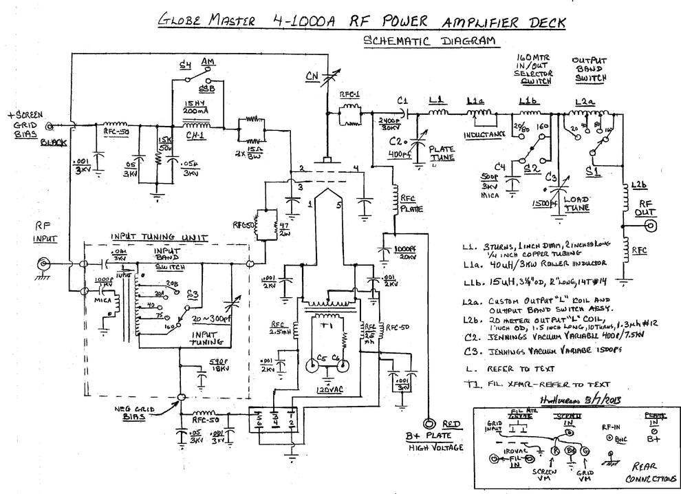
SCHEMATIC DIAGRAM

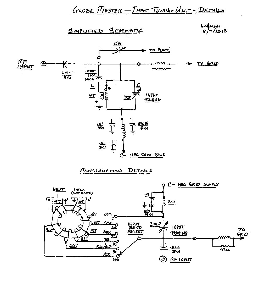
INPUT TUNING UNIT
SCHEMATIC AND WIRING DIAGRAM

CIRCUIT DESCRIPTIONS
CONTROL GRID INPUT CIRCUIT
RF from the exciter is connected to the RF INPUT jack of the amplifier via connection to either the EXCITER INPUT or TRANSCEIVER INPUT SO239 connectors located in the inside back door section of the lower cabinet. The 4-1000A is grid driven through a band-switchable tuning unit and requires a drive signal of only 12 watts or so to deliver full power to the load.
The INPUT TUNING UNIT serves both as a parallel-tuned input band trap and a negative feedback neutralization transformer in addition to the control grid bias voltage source. Input coil (L) is tapped and switched at various points as indicated in the TUNING UNIT WIRING DIAGRAM. Variable input tuning capacitor (C) allows wide band tuning on and past any band selected by the INPUT BAND SELECTOR switch. The tuning unit was not originally built by the author, only modifications to the present configuration were made to accommodate neutralizing and input tuning; therefore the composition of core material (L) is unknown. Same holds true for output coil (L2a), so don’t ask what they are, because I don’t know.
Some attempted configurations to the input tuning unit were link-coupling; which failed miserably when driven by a “solid state” rig-SWR problems. Too much drive was required when driven by a 6146 X 2 rig. Also attempted <for supposable amplifier stability>was grid swamping resistors. This just added more load to the exciter causing the exciter to run hot plus I was unable to get full output due to now “lack of drive power”.
I could not find a real solution for neutralization, as split-variable-tuning capacitors are very difficult to find these days; and the tuning unit had already been built. Being worried about the real problem of amplifier instability and parasitic “thermo-nuclear” runaway… (Metzler’s Law: “Every Amplifier Wants to be an Oscillator”), I was unsure on how to prevent building a GIANT OSCILLATOR in the first place.
It just
so happened I was reviewing some schematics in the back of the RCA TT5
tube manual when I stumbled across something very interesting in the
grounded-grid 811A amplifier project. I noticed a tertiary winding on
the input tuning coil going to the neutralizing capacitor and tied to
the plate circuit of the 811A’s. The tertiary winding was connected so
that the signal returning from the plate was 180 degrees out of phase
with the input signal. This “enlightenment” was absolutely ingenious!
No split-capacitor needed! I would envision this circuit to perform
similarly to what the AUDIO PHOOLS call “NEGATIVE FEEDBACK”.
I thought it would work something like this: I would properly neutralize the amplifier on 40 meters and as the operating frequency went up the additional coupling of the neutralizing capacitor (CN) would add more and more negative feedback to the input stage. This would automatically produce a “rolling-off” of the higher frequencies. Hopefully well before the “parasitic range” was reached, there would actually be less than unity gain of the amplifier and oscillation could not occur. I hope I’m right here, but so far it has worked very well. Only drawback I see is that as the operating frequency is increased, more drive power would be needed for the same output. However, with the very low power needed to drive the amplifier to full output, this has not been an issue.
SCREEN GRID CIRCUIT
The screen grid voltage is a direct function of the position of the plate voltage OUTPUT CONTROL Variac, as the primaries of the plate and screen transformers are both connected in parallel. Therefore, as the plate voltage is increased, the screen voltage increases as well.
There are normally two methods used to develop screen bias. One is to use bias dropping resistors using the plate voltage as the source and the other is using a separate fixed bias supply. There are pros and cons to both.
Screen Dropping Resistors:
Pros:
If a plate voltage malfunction occurs (loss of plate voltage), screen voltage would disappear as well thus preventing damage to the tube caused by excessive screen current.
Screen voltage would follow the plate voltage; excellent for AM.
Cons:
Lots of heat burned-up in the screen resistors! For example, assuming plate voltage of 3kV, maintaining 500V @ 100ma on the screen grid would cause the dropping resistors to produce 250W of heat.
Fixed Screen Supply:
Pros:
Provides a stable voltage source at relatively low power consumption. Poor for high level AM reproduction unless special issues are addressed. (I’ll talk about this a bit later)
Cons:
Current limiting fuses or other special circuitry must be provided to protect the screen grid in the event of loss of plate voltage. Low impedance path to ground must be provided to the screen grid at all times.
Due to the excessive amount of heat produced by dropping resistors, I chose to use a separate fixed bias supply with a low impedance path to ground.
William Orr, K6SAI, describes numerous times in his Radio Amateur Handbook, that the screen MUST NEVER BE ALLOWED TO BE DISCONNECTED FROM IT’S LOW IMPEDANCE SOURCE, EVEN FOR A SPLIT SECOND, AS THE SCREEN VOLTAGE WOULD INSTANTLY EXCEED IT’S RATING AND THE TUBE WOULD BE DESTROYED. THE TIME IT TAKES FOR A TOGGLE SWITCH TO TRANSITION FROM ONE STATE TO ANOTHER IS TOO LONG!
This problem was addressed by the permanent addition of a 15K/50W screen protection resistor connected from screen to ground. This provides the low impedance path to ground, AND, by connecting the screen and plate supplies to the same power source, both supplies SHOULD shut down or be energized at the same time.
A toggle switch on the front panel allows the secondary of the screen transformer to be switched from the HIGH to LOW power setting. This reduces the screen voltage approximately in half for tuning purposes.
THE SCREEN MODULATION CHOKE
During
initial testing the RF deck performed reasonably well. Great SSB and
Low Level AM reports. Things changed considerably when we tried to
use the 304TL Plate Modulator. Audio levels in excess of 30% would
cause arcing in the RF deck and on the modulation transformers’
protective spark gap. We knew that there some
impedance mismatch between the modulator and the PA , but
not that much. We
decided to add small 2.5H/150mA choke in series with the 4-1000A
screen grid, which reduced the arcing somewhat.
The WRL Globe King 500 series transmitter, for example, uses a choke
in series with the screen, but only in the AM mode. I read or heard
somewhere that when the screen choke method of modulation is
employed, the value of the choke should be somewhere in the 10~20
Henry range.
We were able to obtain a large 15H/200mA choke and swapped it out with the 2.5H/150mA one. Wow! What a difference! Some arcing does occasionally occur when the modulation level is well in excess of 100%, but not very often. There has been much local discussion as to exactly why the screen choke is needed in the high level modulation mode, some of which concluded that the high-wattage screen dropping resistor method allows the screen grid to “swing in phase with the plate current”. The screen choke does something similar, but some audio phase distortion is expected to be encountered. One thing we do know for sure is that hi level modulation doesn’t work well without one or the other. A bypass switch labeled MODE AM/SSB was added to the front panel of the RF deck so that the screen choke may be bypassed when using the RF deck as a stand-alone amplifier.
Pi-L TANK NETWORK
The RF deck utilizes a Pi-L tuning network consisting of Plate Tuning Capacitor C2, Primary Tuning Inductance L1, L1a and L1b, Output Loading Capacitor C3, and Output Inductors L2a and L2b. The Pi-L network provides excellent second harmonic suppression. Values were chosen from the Pi-L chart in the William Orr, W6SAI, Radio Handbook.
C2 (PLATE TUNING) is a 400pf vacuum variable capacitor.
L1 is the 20 meter coil.
L1a (INDUCTANCE) is a 40uH roller inductor.
L1b adds an additional 17uH of inductance to L1a in order to cover the 160 meter band which is controlled by switch S2. Switch S2 also adds 500pf to the loading tuning capacitor (C3) in the 160 meter mode.
C3 (LOAD TUNING) is a 1500pf vacuum variable capacitor.
L2a is the output “L” part of the Pi-network and is band switched via control S1. I am not sure of the origin of this coil other than I was told that it is “commercially available for just this purpose”. It seems to work very well.
L2b is the 20 meter portion of L2a, see schematic for additional details.
RFC at the RF output connector provides for a DC reference.